Mastering Circuit Board Components: Identify, Test & Choose

Table of Content
- 1. Introduction: Unlocking the Language of PCBs
- 2. What Exactly is a Printed Circuit Board (PCB )?
- 3. Mastering PCB Components Identification: A Visual & Practical Guide
- 4. Essential Tools for Component Identification and Testing
- 5. Practical Steps for Testing Common PCB Parts
- 6. Choosing the Right Electronic Components for Your Project
- 7. FAQ: Your Component Questions Answered
- 8. Summary: Become a PCB Component Expert
- Key Takeaways
1. Introduction: Unlocking the Language of PCBs
Ever gazed at the intricate maze of tiny parts on a circuit board and wondered what they all do? From the smallest resistor to the most complex integrated circuit, each component plays a vital role in bringing electronic devices to life. Understanding these fundamental building blocks is not just for electronics engineers; it’s a crucial skill for hobbyists, technicians, and anyone looking to troubleshoot, repair , or even design their own electronic creations. This guide will demystify the world of circuit board components, offering a comprehensive look at how to identify, test, and ultimately choose the right parts for any application.
Whether you’re looking to reverse engineer an old gadget, perform critical troubleshooting, or simply expand your knowledge, mastering PCB components identification is an indispensable skill. Let’s dive in and transform that jumble of parts into a clear, understandable system.
2. What Exactly is a Printed Circuit Board (PCB )?
Before we delve into the individual components, it’s essential to understand their foundation: the printed circuit board (PCB). A PCB is much more than just a green slab; it’s the backbone of virtually every electronic device. Made typically from layers of non-conductive fiberglass (FR4) laminated with conductive copper traces, the PCB serves as a platform that physically supports and electrically interconnects electronic components.
These copper traces replace traditional wiring, allowing for incredibly compact, reliable, and complex circuits. PCBs can be single-layer, double-layer, or multi-layer, depending on the complexity required, with each layer containing conductive pathways separated by insulating material. This layered design allows for intricate circuit designs to be integrated into a single, compact board, making modern electronics possible.
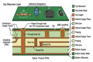
The functionality of any electronic device hinges on these conductive pathways and the array of parts soldered onto them. Without the components, a PCB is just a base; once populated with resistors, capacitors, transistors, and ICs, it becomes a dynamic, functional circuit.
3. Mastering PCB Components Identification: A Visual & Practical Guide
The fastest way to identify circuit board components is by combining visual inspection with a basic understanding of their functions and typical markings. Here’s how to approach it:
3.1. Decoding the Silkscreen: Reference Designators and Markings
The silkscreen layer on a PCB provides crucial clues. It’s the white (or sometimes black/yellow) text and symbols printed on the board surface. Key elements to look for include:
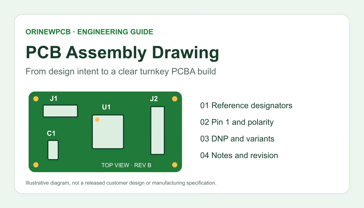
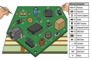
- Reference Designators:These are short alphanumeric codes that label each component. Common ones include:
- R:Resistor
- C:Capacitor
- D:Diode (or LED)
- Q:Transistor (or MOSFET)
- U :Integrated Circuit (IC)
- L:Inductor
- J:Jumper or Connector
- SW:Switch
- TP:Test Point
- Polarity Markings:Many components, like diodes, electrolytic capacitors, and ICs, are polarity-sensitive. The silkscreen will often indicate the positive (+) or negative (-) terminal , or a pin 1 indicator for ICs (a dot or notch).
- Component Outlines:The silkscreen often shows the physical outline of the component, which can help in distinguishing between similar-looking parts or confirming placement.
3.2. Visual Inspection: Package Style and Value Markings
Beyond the silkscreen, the physical appearance of the component itself is key. Components come in various package styles, primarily :
- Through-Hole (THT):These components have leads that pass through holes in the PCB and are soldered on the opposite side. They are generally larger and easier to identify for beginners.
- Surface Mount Device (SMD):These components are smaller and mounted directly onto the surface of the PCB. They are prevalent in modern, compact electronics. SMD components often have tiny codes or numbers printed on them for identification.
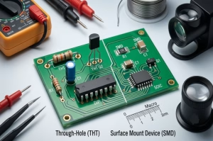
Value markings are also important. Resistors, for example, often use a color code (for THT) or numeric codes (for SMD) to indicate their resistance value. Capacitors might have capacitance values, voltage ratings, or polarity indicators printed on them.
3.3. Common Types of Electronic Components and Their Functions
Here’s a breakdown of the most common electronic components you’ll encounter:
| Component Type | Reference Designator | Common Appearance | Primary Function |
| Resistor | R | Cylindrical (THT, color bands), small rectangular (SMD) | Limits current flow, divides voltage |
| Capacitor | C | Cylindrical (electrolytic), disk/ceramic (THT), small rectangular (SMD) | Stores electrical energy, blocks DC, passes AC |
| Diode | D | Small cylinder with a band (THT), small rectangular with a line (SMD) | Allows current in one direction, blocks reverse |
| Transistor | Q | Three leads, various plastic packages (THT/SMD) | Amplifies or switches electronic signals |
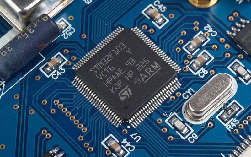
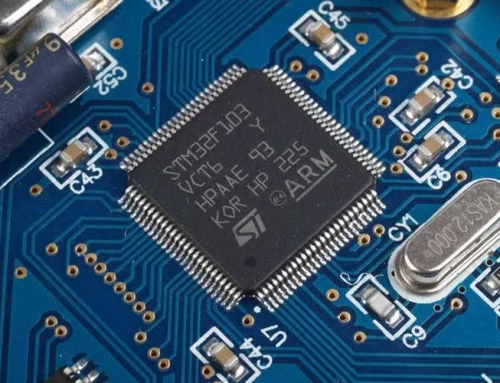
| Integrated Circuit (IC) | U | Black rectangular package with many pins (THT/SMD) | Performs complex functions (microprocessors, memory, logic gates) |
| Inductor | L | Coil of wire, various shapes (THT/SMD) | Stores energy in a magnetic field, filters signals |
| Connector | J, CN | Plastic/metal sockets or pins | Provides removable electrical connection |
| Switch | SW | Various types: push-button, toggle, slide | Opens/closes a circuit |
| Relay | K | Box-shaped, multiple pins | Electrically operated switch |
4. Essential Tools for Component Identification and Testing
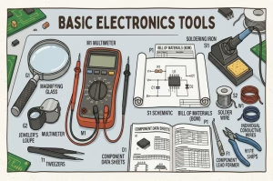
To effectively identify and test components, you’ll need a few basic tools:
- Multimeter:An indispensable tool for measuring voltage, current, and resistance. Many also offer capacitance, continuity, and diode test functions.
- Magnifying Glass or Jeweler’s Loupe:Essential for reading tiny markings on SMD components.
- Tweezers:Useful for handling small components and for test leads.
- Schematics and Bill of Materials (BOM): If available, these documents are the ultimate guides. A schematic shows the circuit’s design, and the BOM lists every component with its specifications.
- Component DataSheets: Detailed documents provided by manufacturers for specific components, containing all electrical and physical specifications.
5. Practical Steps for Testing Common PCB Parts
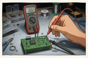
Testing PCB parts is crucial for troubleshooting faults and verifying component integrity. Always ensure power is OFF before testing passive components like resistors and capacitors directly on the board to avoid incorrect readings due to parallel circuits.
5.1. Resistor Testing
Set your multimeter to resistance (Ohms Ω) mode. Measure across the resistor terminals. The reading should match the marked value (within tolerance). A significantly higher or infinite reading indicates an open circuit; a very low or zero reading suggests a short.
5.2. Capacitor Testing
For most capacitors, set your multimeter to capacitance (F) mode. Measure across the terminals. The reading should be close to the marked value. For electrolytic capacitors, observe polarity. Many mult imeters also have a continuity test; a shorted capacitor will show continuity, which is usually a fault. A quick charge/discharge cycle (indicated by a rising then falling resistance on an analog meter) can also verify functionality.
5.3. Diode Testing
Use the diode test mode on your multimeter. Connect the red probe to the anode and the black probe to the cathode (banded side). You should see a voltage drop (typically 0.3V for germanium, 0.7V for silicon, and 1.5-3V for LEDs). Reverse the probes; the meter should read “OL” (open loop) or infinite resistance, indicating no current flow. If it reads a voltage drop in both directions or infinite in both, the diode is likely faulty.
5.4. Transistor Testing
Transistor testing can be more complex, but a basic check involves using the diode test mode. For an NPN transistor, connect the red probe to the base and the black probe to the emitter and collector in turn. You should see a diode drop. Reverse the probes; you should see ” OL.” Repeat for the collector-emitter junction (should be OL in both directions unless faulty). Some multimeters also have hFE (gain) test sockets for more comprehensive checks.
5.5. Continuity Checks
Use your multimeter’s continuity mode (often an audible beep). This is excellent for checking traces on the PCB for breaks (open circuits) or unwanted shorts between adjacent traces or component pins.
6. Choosing the Right Electronic Components for Your Project
Selecting the correct components is as crucial as identifying them. When choosing components, consider the following:
- Functionality:Does the component perform the required electrical task (e.g., current limiting, signal amplification, data processing )?
- Specifications:Match electrical parameters like voltage rating, current capacity, resistance, capacitance, frequency response, and power dissipation to your circuit’s needs. Overspecifying can add unnecessary cost, while underspecifying can lead to failure.
- Package Type (SMD vs. THT):This depends on space constraints, manufacturing capabilities, and ease of assembly/repair. SMD components are smaller and suited for automated assembly, while THT parts are easier for manual soldering and prototyping.
- Cost and Availability:Balance performance with budget. Consider lead times and the reliability of your sourcing components.
- Reliability and Quality:For critical applications, opt for components from reputable manufacturers with proven reliability.
- Environmental Factors:Consider operating temperature range, humidity, and vibration requirements.
7. FAQ: Your Component Questions Answered
- Question1:What is a reference designator?
Answer: A reference designator is an alphanumeric code (e.g., R1, C5, U2) printed on the PCB’s silkscreen layer next to a component. It uniquely identifies that component on the board and correlates with entries in the schematic and Bill of Materials (BOM). - Question2:How can I identify SMD components without clear markings?
Answer: SMD components can be challenging due to their small size and cryptic codes. Besides package size and type, cross-referencing with a circuit schematic or BOM is the best approach. Online SMD code lookup databases can also help decipher common numeric/alphanumeric codes. When in doubt, desoldering and testing with a multimeter can confirm its type (e.g., resistance, capacitance). - Question3:Is it safe to test components while they are still soldered to the PCB?
Answer: For passive components like resistors and capacitors, it’s generally best to desolder them for accurate readings, as other components in the circuit can create parallel paths and skew measurements. For active components like ICs and transistors, basic voltage checks can be done with power on, but more thorough testing (e.g., diode checks, resistance) usually requires the component to be isolated or desoldered, and always with power off. - Question4:What’s the difference between a resistor and an inductor visually?
Answer: While both can be cylindrical, resistors (especially THT) typically have color bands and are usually made of carbon film or metal film. Inductors are essentially coils of wire, sometimes visible, or encapsulated in a ferrite bead. Visually, inductors are often thicker or more robust looking than resistors of similar size, and they generally lack color bands.
8. Summary: Become a PCB Component Expert
Navigating the world of circuit board components might seem daunting at first, but with a systematic approach to identification, the right tools for testing, and a clear understanding of selection criteria, anyone can become proficient. We’ve covered the fundamentals of the printed circuit board, how to interpret silkscreen markings and reference designators, the characteristics of common electronic components, and practical methods for testing PCB parts. By applying these insights, you’re now equipped to confidently identify, troubleshoot, and choose the precise parts for your electronic endeavors, unlocking a deeper understanding of the devices that power our modern world.
Key Takeaways
- Circuit board components identification relies on a combination of visual inspection, silkscreen markings, and understanding package types (THT vs. SMD).
- Reference designators (R, C, D, Q, U, J) provide quick clues to a component’s type and function.
- A multimeter is an essential tool for testing components like resistors, capacitors, and diodes.
- Always turn off power before testing components directly on a PCB to ensure accurate readings and safety.
- When choosing components, consider specifications, package type, cost, availability, and reliability to ensure project success.
OrinewPCB has focused as a one-stop PCB assembly manufacturer from PCB Manufacturing to Electronic Components Sourcing to PCB Assembly to Test to Program IC for more than 14 Years with reliable quality and fastest delivery for global clients.
Related Posts
ORINEWPCB · PROJECT SUPPORT
Contact Us
Discuss your PCB assembly project with our team.
FREE QUOTE
Plan your turnkey PCBA build.
Share your quantity and requirements. Add Gerber files and a BOM when ready.
Files are optional for an initial discussion. Include any assembly, sourcing or testing requirements in your message.