PCB Functional Test Plan: A Production Handoff Checklist
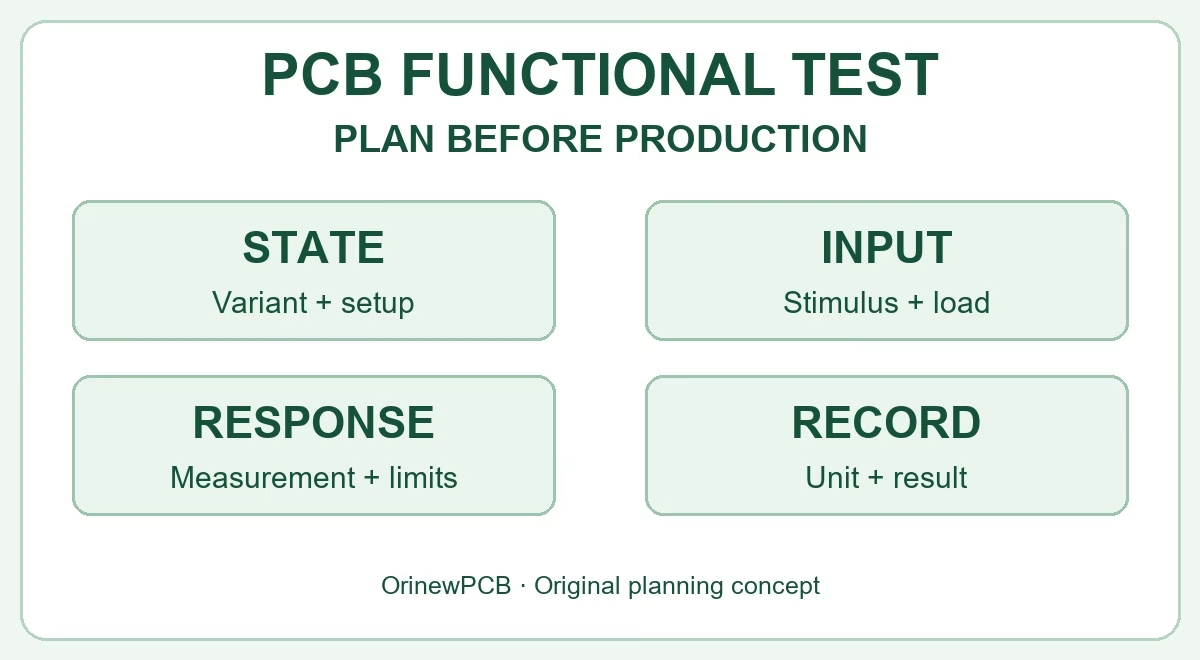
Table of Content
- 1. Define what a functional test must prove
- 2. Freeze the unit identity and map variant coverage
- 3. Write each test as a reproducible instruction
- 4. Agree conditions and limits before running the batch
- 5. Release the fixture and verify the test system
- 6. Example: document a small-batch functional test
- 7. Retain useful records and control retesting
- 8. Include functional testing in the turnkey PCBA quote
- PCB functional test plan FAQ
PRODUCTION TESTING · ENGINEERING TO SUPPLIER HANDOFF
Quick answer: A PCB functional test plan tells an assembly supplier how to put a specific board variant into a defined operating state, apply the required inputs and loads, measure its response, decide pass or fail, and retain the result. To make that plan usable in production, include the hardware and firmware identity, fixture connections, test conditions, limits, timing, exception handling and record requirements.
“Power it on and check that it works” leaves important decisions unresolved. A board can boot while an output, sensor channel or communication interface remains untested. A useful handoff replaces that ambiguity with repeatable instructions and an agreed acceptance scope.
This guide focuses on writing and releasing a functional test plan for turnkey PCBA. Use the checklist and illustrative test rows below when you prepare a new build or ask a supplier to quote the testing work.
For a current build, send your PCB files, BOM and available test requirements for a turnkey PCBA review, including any open decisions that still need engineering approval.
1. Define what a functional test must prove
Functional circuit testing, often called FCT, exercises selected operating functions of an assembled board under specified conditions. Depending on the product, that can mean checking power behavior, analog responses, digital inputs and outputs, communication transactions or an application-specific sequence.
Structural checks and functional checks answer different questions. AOI examines visible assembly features; ICT or flying-probe programs check selected electrical connections or components within their coverage. A functional test asks whether the released assembly produces the required behavior. Passing one method does not establish complete coverage by the others.
Start by naming the shipped state: assembled board only, programmed PCBA, calibrated board, coated assembly or a completed product in an enclosure. Then define where production acceptance ends. Environmental qualification, EMC, regulatory compliance, long-term life and every possible use condition are separate requirements unless explicitly included.
A product test is not the test station’s self-check. A fixture can communicate successfully with its instruments while a DUT connection is missing. A unit can also pass a basic boot check without exercising its fitted features. State what the board must demonstrate and separately define how the station’s readiness is established.
2. Freeze the unit identity and map variant coverage
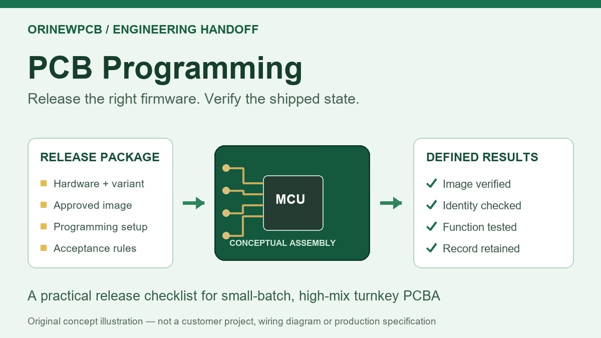
The test plan needs a controlled identity just like the PCB and BOM. Record the assembly number, PCB revision, fitted BOM variant, firmware/configuration identity and test-plan revision. If programming is part of the build, keep the approved image and configuration handoff in the PCB programming release package; the functional plan should identify the expected operating state without duplicating uncontrolled firmware files.
| Function or condition | Define for each variant | Avoid this gap |
|---|---|---|
| Power and startup | Permitted supply conditions, startup behavior, operating mode and required measurements. | Treating a lit power LED as proof of all rails and functions. |
| Analog or sensor channel | Which fitted channels are exercised, applied input, load, measurement point and accepted response. | Testing one channel while reporting that every channel passed. |
| Digital interface | Connector/pin mapping, levels, protocol configuration, transaction and expected data or response. | Counting a detected port as a successful application-level exchange. |
| Output or actuator interface | Required load or approved simulator, commanded states and observed output behavior. | Checking only an unloaded output that behaves differently in use. |
| Optional or not-fitted feature | Explicit variant applicability and the reason a check is not required. | Silently skipping a required test or failing a legitimate not-fitted option. |
This is a planning matrix, not a universal test list. Product engineering should decide the required coverage and any sampling policy. For high-mix orders, a shared PCB layout does not mean the same test sequence and limits apply to every fitted configuration.
3. Write each test as a reproducible instruction
A good test row lets another qualified person reproduce the check without guessing. Separate what is applied, what is measured and how the result is judged. Use unique test IDs so a failed result can be traced to its requirement, work instruction and corrective action.
| Field | What to enter | Why it is needed |
|---|---|---|
| Test ID and requirement | A stable identifier and the approved requirement or acceptance objective. | Connects a result to the function being accepted. |
| Variant and starting state | Applicable assembly variants, firmware/configuration, operating mode and prerequisite results. | Prevents the right measurement from being taken in the wrong state. |
| Connection and setup | Released fixture/harness mapping, reference or return, instrument configuration and required accessories. | Removes assumptions about connector orientation, measurement location and loading. |
| Stimulus and load | The input, command or load to apply, with units, tolerances and any required sequence. | Defines the condition under which the response has meaning. |
| Timing and acquisition | Settling condition, measurement interval, timeout, sample handling and method where relevant. | Distinguishes startup transients, steady operation and missing responses. |
| Acceptance rule | Approved lower/upper limits or expected response, comparison rule and treatment of uncertainty. | Makes the pass/fail decision explicit. |
| Failure and cleanup | Abort/continue policy, safe state, unit hold, permitted retries and escalation. | Prevents a failure from becoming an uncontrolled retest or an unsafe next step. |
| Retained result | Measured value or response, units, status and the unit/station/revision identifiers to retain. | Provides evidence beyond an isolated green “PASS” label. |
For a communication check, “UART OK” is incomplete. Identify the physical interface, electrical requirements, serial settings, requested transaction, expected response and timeout. For an analog check, name the applied input, load, measurement location, units and decision limits.
4. Agree conditions and limits before running the batch
Use approved product requirements to set acceptance criteria. A working prototype is useful reference material, but its measured value is not automatically the correct production limit. Component variation, operating state, load, measurement method and instrument uncertainty can all affect the decision.
- Separate startup from steady operation. Define the relevant timing or settling criterion. A single current limit or one late measurement may not capture the behavior the requirement intends to assess.
- Review both sides of a requirement. An upper current limit alone may not reveal a circuit block that never enabled. Decide which lower limits, functional responses or other checks are actually appropriate for the design.
- Define the measurement path. Connector contact, cable loss, grounding and fixture loading may affect the quantity being measured. Identify the intended reference and measurement point.
- State the decision rule. Specify whether boundaries are inclusive, how rounding is handled, and how uncertainty or guard bands are treated where relevant. Do not silently widen limits to make unstable results pass.
- Control changes. A new limit, firmware image, load or fixture revision may require review of the affected checks before production resumes.
Safety-related connections, protective measures, supply sequencing and failure shutdown must be engineered for the actual product and equipment. A general blog checklist cannot provide an approved power-up procedure for an unknown board.
5. Release the fixture and verify the test system
A functional test can be manual, automated or mixed. The important requirement is a controlled, repeatable method with the necessary access and evidence. Low quantity does not automatically eliminate the need for a fixture, and automation does not automatically prove that the selected tests detect the intended faults.
Provide a released interface drawing or connection table, including board orientation, connector identities, pin mapping, reference/return connections, required loads or simulators and any prohibited connections. Review mechanical support, access before coating or enclosure closure, and protection against connecting the wrong variant. Agree who supplies, owns, stores and maintains any tooling.
- Confirm station setup, software and limits revisions, instrument identities and calibration requirements.
- Verify fixture/harness connectivity and readiness using an approved method; identify consumable contacts and maintenance checks where needed.
- Demonstrate repeatability on representative units and appropriate setups. One successful run is limited evidence.
- Use approved known-fault samples or suitable simulations to check that required failures are detected, without introducing uncontrolled damage.
- Distinguish a station or connection error from a valid DUT failure. A missing response caused by a disconnected cable is not the same result as a measured out-of-limit output.
- Review affected coverage after fixture repair, instrument replacement, software changes or product revisions.
A reference or “golden” unit can support station checks, but it should have controlled identity and known status. It does not replace released requirements, traceable measurement practice or evidence that the test responds correctly to the faults it is supposed to detect.
6. Example: document a small-batch functional test
Illustrative document example—not a customer case or a test recipe: a team plans two variants of a control board. Both have a regulated supply rail and a communication interface; only Variant B has an optional output stage. The plan identifies each unit and variant before selecting its checks.
| Test row | Released instruction needs | Recorded example or decision |
|---|---|---|
| FCT-01: supply rail | For this fictitious example only, assume engineering has approved a 4.75–5.25 V inclusive acceptance window under a separately defined supply, load and measurement method. | Measured 5.03 V: passes this example’s numeric comparison. Retain the value and units. These values are not recommended limits for your design. |
| FCT-02: communications | The released transaction, interface configuration, expected response and timeout, using the applicable firmware state. | Store the response/status and any required timing evidence. A timeout or wrong response must not be recorded as a pass. |
| FCT-03: optional output | Variant B only: defined stimulus, approved load, measurement and acceptance criteria. Variant A: explicitly not applicable. | A missing required result on B holds the unit. The not-applicable status on A is linked to the variant rule, not a generic “PASS.” |
The sample voltage row illustrates the document structure only; it does not establish a complete test, instrument capability or uncertainty decision. Before use, the actual plan must define all conditions and engineering-approved acceptance rules. A measured value without its state and method cannot be interpreted reliably.
Keep production acceptance separate from debugging. A technician may investigate a failure using additional measurements, but those measurements and any repair need an approved disposition. Repeating the same test until one reading passes hides useful evidence and does not resolve the cause.
7. Retain useful records and control retesting
Agree the records before the order, including the format and delivery scope. A practical unit record links the assembly/variant and unit identifier to the test-plan and software revisions, fixture/station identity, date, required measured values or responses, limits and final status. Include the information necessary to reproduce and interpret a failure.
Keep pass, fail, error, aborted and not-applicable/skipped outcomes distinct under the agreed rules. A required check that never ran cannot support a passing acceptance decision. Preserve earlier attempts, failure information and any approved rework or retest rather than replacing the history with the latest pass.
Define who may authorize a retry, change a limit or release a held unit. If rework occurs, state which inspections and tests must be repeated. Required records and traceability are project-specific; do not assume every build includes the same report or retention period.
8. Include functional testing in the turnkey PCBA quote
A test plan also defines commercial scope. Fixture and software preparation, loads or simulators, unit handling, execution time, variant changeovers, calibration and maintenance needs, reporting and failure investigation can affect the quotation and schedule. Separate one-time preparation from recurring testing and identify work that is still undefined.
- PCB, BOM and assembly revisions; fitted variants and quantities for each build.
- Required shipped state and approved firmware/configuration identity.
- Functional coverage matrix and the current test-plan status, including open engineering decisions.
- Connector/pin mapping, fixture/harness files, approved loads, instruments or supplied tooling, and ownership responsibilities.
- Acceptance limits, operating conditions, timing and the agreed station-validation approach.
- Inspection and electrical test requirements in addition to functional acceptance, with any required sample or unit coverage.
- Result format, unit identification, retest/repair authorization and shipment-release requirements.
- Required delivery date and destination, plus component sourcing or substitution constraints.
OrinewPCB provides one-stop PCB assembly covering PCB production, component sourcing and assembly coordination, with a particular focus on small-to-medium, high-mix builds. Its policy is to supply and assemble with 100% new, original and genuine components. Cooperation with component manufacturers and distributors supports review of BOM pricing and availability; actual offers and delivery plans require project confirmation.
The company’s nine-step PCBA quality workflow provides a basis for discussing quality requirements. Specify the functional checks needed for your build rather than assuming that a named workflow covers every product function. Bare-PCB flying-probe electrical testing and assembled-product functional acceptance are separate scopes. Learn more at the OrinewPCB brand website.
Ask for a quote that includes the required test scope
Send your PCB files, BOM, quantities and functional test requirements for a coordinated turnkey PCBA review. If the test procedure is incomplete, send the current requirements and identify the missing items so responsibilities, preparation work and acceptance can be clarified before release.
Request a Turnkey PCBA & Test-Scope Review
Include your required date, destination, variant quantities and any customer-supplied fixture or software.
PCB functional test plan FAQ
Is a functional test the same as ICT or flying-probe testing?
No. Functional testing exercises defined operating behavior. ICT and flying-probe programs check selected connections or components within their access and program coverage. A production strategy can combine methods, but each method needs its own scope and acceptance criteria.
Can I send a working sample instead of a written test plan?
A controlled reference sample can help, but it does not fully define conditions, limits, timing, variants or failure handling. Provide the written requirements and identify what the sample is intended to demonstrate. Its measured values should not silently become production limits.
Do small batches need an automated functional test fixture?
Not always. A documented manual or mixed procedure may be appropriate, while some boards need dedicated access or load hardware even at low volume. Compare coverage, repeatability, handling, execution time, variant changes and total preparation cost for the actual build.
Does “100% tested” mean every function is covered?
No. It can describe unit coverage for an agreed test, but does not by itself define functional or fault coverage. Ask which checks run on which units, under which conditions, against which limits, and which results are retained.
Who defines functional test limits and approves changes?
Product requirements and engineering review should establish the acceptance rules, with responsibilities agreed between customer and supplier. Control changes to limits, firmware, fixtures and methods, and reassess affected checks before using the changed plan for production acceptance.
Can you quote turnkey PCBA before my test procedure is complete?
You can request an initial scope review with your available files and requirements. Clearly identify open items, any supplied tools and who will complete the test definition. A final offer should state the assumptions, preparation work and agreed recurring test scope.
Related Posts
ORINEWPCB · PROJECT SUPPORT
Contact Us
Discuss your PCB assembly project with our team.
FREE QUOTE
Plan your turnkey PCBA build.
Share your quantity and requirements. Add Gerber files and a BOM when ready.
Files are optional for an initial discussion. Include any assembly, sourcing or testing requirements in your message.