Circuit Board Components: How to Identify, Test & Choose

Table of Content
- 1. Common circuit board components and what they do
- 2. How to identify components on a circuit board
- 3. Prepare a useful component test
- 4. What a multimeter can and cannot tell you
- 5. Choose parts by application, not appearance alone
- 6. Turn the identification into a build-ready BOM
- 7. Circuit board component FAQ
CIRCUIT BOARD COMPONENTS · IDENTIFICATION, TESTING & SELECTION
Quick answer: Identify circuit board components by combining the reference designator, package and top marking with the schematic, BOM and manufacturer datasheet. A board label such as U3 locates a part; it is not an orderable part number. Use a multimeter for appropriate basic checks after isolating power and stored energy, but account for other paths in the circuit. Before buying a replacement or releasing a PCB assembly, confirm the exact manufacturer part number, ratings, pinout, footprint and approved source.
A familiar-looking black package or a matching resistance reading is only part of the evidence. Hardware engineers need a repeatable way to distinguish what a component looks like, what it is and whether it is suitable for the build. This guide connects those three questions, from an unknown part on a board to a controlled component choice for production.
Already have a design ready to build? Send the released BOM, PCB files and quantities for an OrinewPCB turnkey PCBA and BOM review. A clear part identity makes sourcing, assembly and test planning more efficient.
1. Common circuit board components and what they do
A bare printed circuit board provides conductive connections and mechanical support. A populated PCB assembly, or PCBA, adds components that perform the electrical functions. Surface-mount devices attach to surface pads; through-hole parts have leads or terminals inserted through board holes. Either construction can contain very different component functions.
Use this table as a starting point. Reference letters are common conventions, not a guarantee; the project’s schematic and library definitions take precedence.
| Component / common label | Typical role and visual clue | What to confirm |
|---|---|---|
| Resistor · R | Sets current, bias or voltage ratios. May be a color-banded axial part or a small rectangular chip. | Resistance, tolerance, power, voltage and package. Not all chip resistors are marked. |
| Capacitor · C | Stores electric-field energy; used for decoupling, filtering and timing. Can be a ceramic chip, can or molded package. | Capacitance, voltage, dielectric, ESR and any polarity. Similar-looking ceramics can have different values. |
| Inductor / ferrite · L or FB | Stores magnetic energy or suppresses noise. Can be wound, shielded or chip-shaped. | Inductance or impedance curve, current rating, saturation, DC resistance and size. |
| Diode / LED · D | Rectification, protection or light emission, depending on type. A band or symbol can indicate orientation. | Device type, polarity, current/voltage and package; a TVS is not interchangeable with a rectifier. |
| Transistor / MOSFET · Q | Switching or amplification. Small plastic packages can resemble diodes or ICs. | Exact pinout, device type, drive conditions, ratings and thermal requirements. |
| Integrated circuit · U or IC | Logic, processing, memory, analog or power control. May have exposed leads or hidden terminals. | Full MPN and suffix, package drawing, pin 1, supply limits and configuration. |
| Connector · J, P or CN | Connects boards, cables or external equipment. Often recognizable by mating contacts. | Pitch, pin count, keying, contact numbering, mating part and current rating. |
| Switch / relay · SW or K | Changes a circuit connection mechanically or electrically. | Contact arrangement, load rating and, for relays, coil drive and isolation requirements. |
| Crystal / test point · Y or X / TP | A crystal supports an oscillator; a test point provides circuit access. These serve different purposes. | Crystal electrical/load specifications or the test-point net and intended access method. |
Browse our electronic components categories when you know the part family. For a production inquiry, send the exact MPN and quantity rather than only a description such as “8-pin IC” or “10 µF capacitor.”
2. How to identify components on a circuit board
Step 1: Record the board and component location
Photograph both sides of the board, its revision marking and the part’s surroundings. Record the reference designator, such as R12 or U3. Find that designator in the matching schematic and BOM. Using a schematic from a different revision can create a convincing but incorrect identification.
Step 2: Read the marking without assuming it is a full part number
Copy every legible line, logo and orientation mark. Small packages may carry an abbreviated device code alongside manufacturing trace information. A top code is a clue to check against the manufacturer’s marking information; it is not automatically the full ordering code. A short marking may fit more than one candidate.
For familiar resistor formats, a marking of 103 can mean 10 × 10³ Ω, or 10 kΩ, while 4R7 can mean 4.7 Ω. These examples apply to the relevant numeric marking system, not every resistor technology or code scheme. A three-digit capacitance code of 104, when specified in picofarads, means 100,000 pF = 100 nF. Unmarked ceramic chip capacitors cannot be reliably identified by color or dimensions alone.
Step 3: Match package, pinout and orientation
Check dimensions, terminal count, lead pitch and package drawing. Confirm whether a drawing shows the top view or bottom view before mapping the pins. “Same package” does not establish the same pinout. A molding dimple is not always the intended pin-1 identifier.
Do not apply one polarity rule to every part. Many aluminum electrolytic sleeves mark the negative terminal, while molded tantalum parts may mark the positive end; KEMET’s T510 drawing is one such positive-stripe example. Confirm the exact component drawing and assembly orientation instead of treating every stripe as negative.
Step 4: Cross-check the circuit role and document uncertainty
Check how the surrounding nets relate to the candidate’s supply, ground, input and output pins. This can reject an implausible match, but it does not replace the exact part documentation. If the BOM is missing or the marking is unreadable, record the part as unconfirmed. Do not release a guessed substitute into a manufacturing BOM.
3. Prepare a useful component test
Basic resistance, capacitance, continuity and diode checks require the circuit to be de-energized. Disconnect all relevant supplies, including batteries and possible back-power from cables, verify the absence of voltage and discharge stored energy using the equipment’s approved procedure. A meter in ohms mode is not a way to establish that an energized circuit is safe. Work involving mains or hazardous stored energy belongs with qualified personnel and suitable procedures.
For low-voltage board work, prepare the matching schematic, a suitable multimeter and leads, magnification and ESD handling. Note the meter mode, test points, board state and expected result before measuring. Keep powered diagnostic voltage measurements separate from passive-component tests and perform them only under an appropriate test procedure.
Power off does not remove parallel paths. A meter measures the network connected between its probes. Other resistors, semiconductor junctions or connected loads can change the result even when every supply is disconnected. Review the schematic and isolate a component only when appropriate; lifting a terminal or removing a part requires controlled rework.
4. What a multimeter can and cannot tell you
| Check | Useful starting point | Limit before declaring a fault |
|---|---|---|
| Resistor · resistance mode | Compare an appropriately isolated measurement with the specified resistance and tolerance. | A low in-circuit result may come from parallel paths. Contact and lead resistance matter for low values. |
| Capacitor · capacitance mode | Measure a safely discharged part using the meter’s specified method and range. | Capacitance alone does not establish ESR, leakage, voltage endurance or behavior under operating bias. |
| Diode · diode mode | For a known simple diode, compare forward and reverse results with its type and test conditions. | Forward voltage depends on device and test current. Parallel paths or insufficient meter voltage can confuse results, particularly LEDs. |
| Trace / connection · continuity | Check the expected connection between specified points on a de-energized circuit. | A beep only reports the meter’s threshold. Inductors, jumpers and low-impedance rails can legitimately show continuity. |
| Transistor / IC · preliminary checks | Look for gross shorts or expected junction behavior when the exact device and circuit are understood. | A BJT junction check is not a universal MOSFET test. Complex IC function, timing and configuration require a defined powered test. |
A simple isolated diode normally conducts under an appropriate forward diode test and blocks in the reverse direction. An unexpected result needs investigation against the actual device and meter conditions; a fixed “0.7 V means good” rule is inadequate. A multimeter’s diode test is also not a substitute for checking a protection diode’s specified breakdown behavior.
Example: a 10 kΩ resistor reads about 5 kΩ on the board. If another 10 kΩ branch is effectively in parallel under the test conditions, their equivalent resistance is 5 kΩ. The measurement alone does not prove the first resistor is defective. Inspect the network, account for the other path and retest an isolated component when justified.
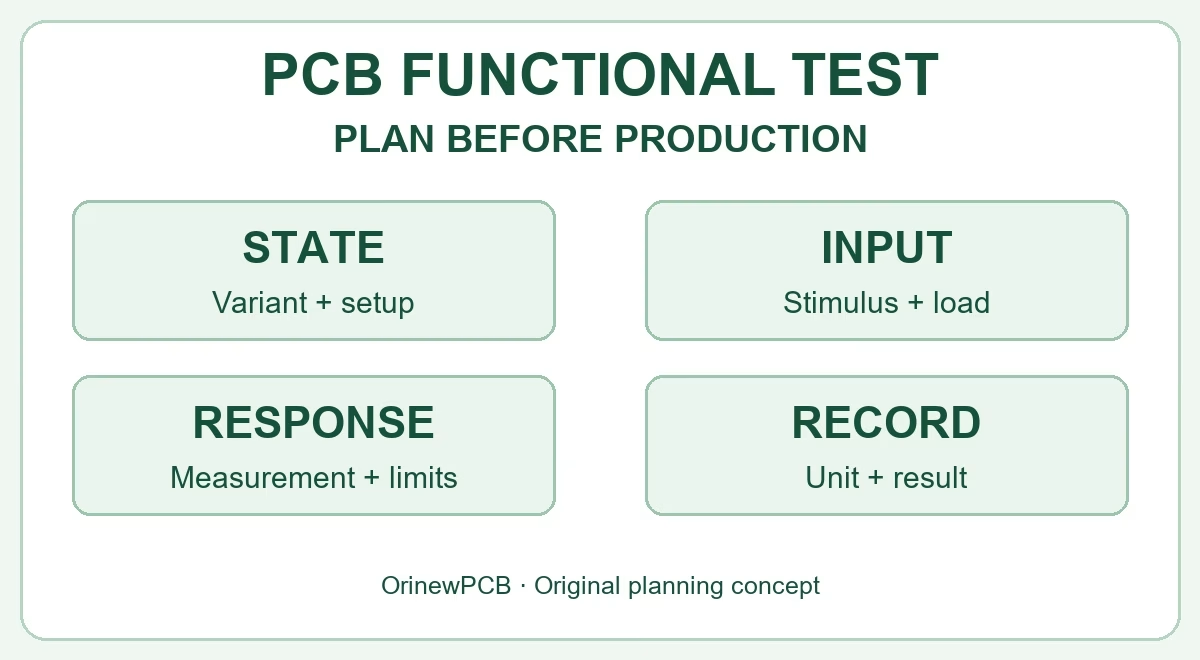
Basic component checks are different from production acceptance of a completed assembly. Use our PCB testing methods guide to distinguish bare-board electrical tests, inspection and assembled-board tests. Define the required functional coverage before the build rather than assuming a meter check proves the product works.
5. Choose parts by application, not appearance alone
A substitute must satisfy the circuit, mechanical fit and manufacturing release. A matching headline value or nominal package name is insufficient. Start from the full manufacturer part number, including the relevant suffix, and compare the parameters that matter in the actual operating conditions.
| Decision | Engineering check | Build / sourcing check |
|---|---|---|
| Electrical behavior | Value, tolerance, operating limits, power, frequency and required temperature range. | Specify the exact approved MPN; document any permissible alternatives. |
| Package and connection | Dimensions, land pattern, pinout, polarity, height and mating requirements. | Verify BOM, placement file and assembly drawing describe the same part. |
| Behavior in use | Thermal conditions, startup/transients, drive requirements and technology-dependent characteristics. | Identify any validation needed before accepting a change. |
| Supply and handling | Required grade, lifecycle status and project-specific compliance requirements. | Review source traceability, packaging, moisture handling, available quantity and quoted lead time. |
For example, two capacitors labeled 10 µF need not provide the same effective capacitance in use. High-permittivity ceramic types such as X5R and X7R can lose capacitance under DC bias. Review the chosen MPN’s operating curves and required circuit margin. A higher printed voltage rating alone is not a complete substitution review.
For a MOSFET, review the on-resistance conditions at the available gate drive, thermal path and relevant switching behavior; gate-threshold voltage alone does not demonstrate that the device is adequately driven. For a connector, pitch and pin count do not prove compatible keying or contact numbering.
Resolve changes through an approved manufacturer and alternatives list. Let the engineering owner approve the candidate against the application before procurement or assembly proceeds. Availability and a lower quoted price should not silently override that approval.
6. Turn the identification into a build-ready BOM
For a small-batch, high-mix assembly, one ambiguous part can affect sourcing, setup and variant control. Use this handoff checklist to connect the component investigation to a usable manufacturing package:
- Identify the release: PCB and assembly revision, BOM revision, project name and intended quantity for each variant.
- Make each line orderable: manufacturer, complete MPN, reference designators, quantity per board and relevant specification.
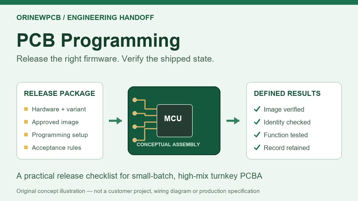
- Define assembly intent: fitted versus DNP parts, polarity/pin 1, special handling and any matched or programmed items.
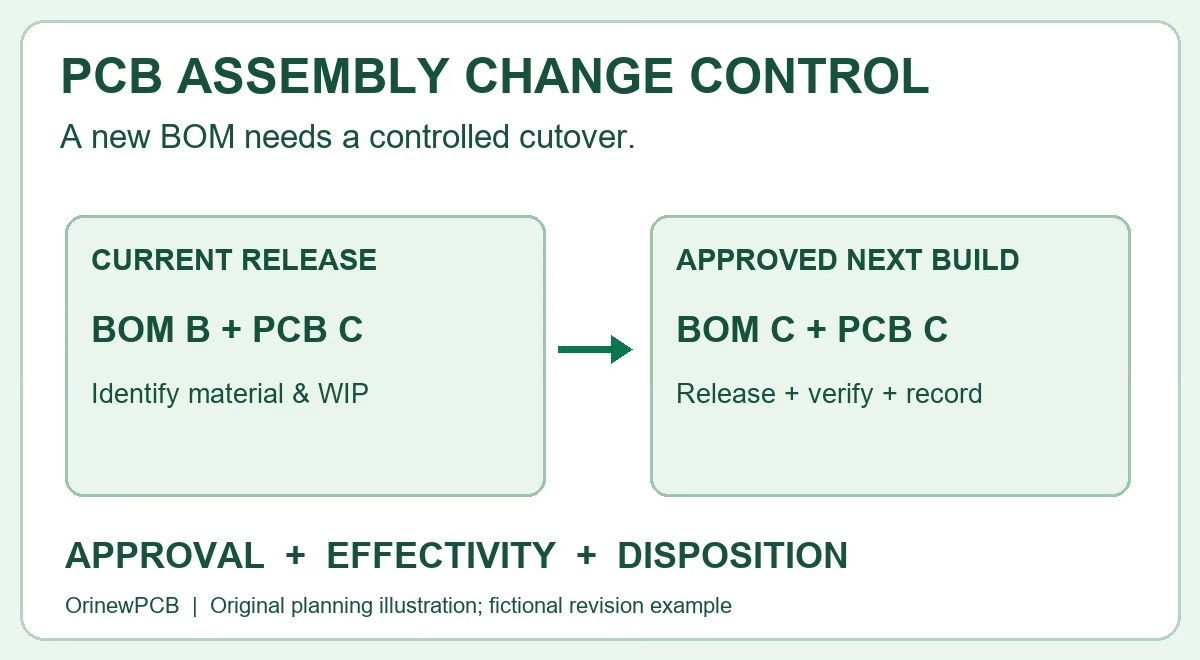
- Control alternatives: approved options, unresolved questions and the person who must approve a proposed replacement.
- Separate supply responsibilities: supplier-procured versus customer-supplied parts, packaging and traceability information.
- Provide manufacturing inputs: PCB fabrication files, placement data and a matching assembly drawing.
- Specify acceptance: required programming, inspection and functional-test inputs; list what evidence is needed before shipment.
OrinewPCB’s component sourcing service supports the procurement side of this process. Our one-stop service combines PCB fabrication, component sourcing and assembly, with a focus on small-to-medium, high-mix builds. We supply and use 100% new, original, genuine components; proposed alternatives require a controlled review rather than an undocumented substitution.
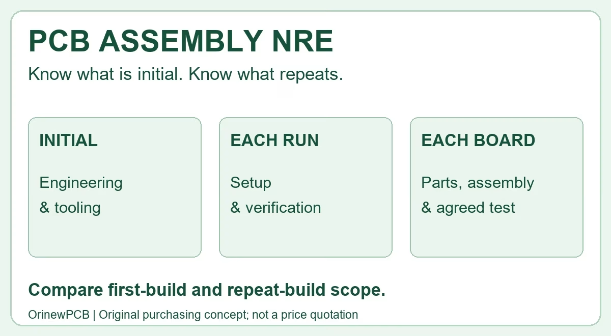
Our PCB fabrication includes 100% flying-probe electrical testing of every bare board. The PCBA quality workflow has nine stages; agree the applicable inspection, programming and functional-test requirements for your project. Bare-board electrical testing and component checks do not replace assembled-product functional coverage. Pricing and delivery depend on the released files, material availability and approved scope.
Need the parts and the assembled boards?
Send your BOM, PCB files, quantities and variants to OrinewPCB. We can review component sourcing together with fabrication, assembly and the required test scope in a full turnkey PCB assembly inquiry. If a part is still unconfirmed, identify the uncertainty and include clear photographs and the matching design information.
Request a Turnkey PCBA & BOM Review
Useful starting package: BOM with exact MPNs · PCB files · quantities/variants · assembly and test requirements · requested delivery date.
7. Circuit board component FAQ
How do I identify an unknown component on a circuit board?
Start with the board revision and reference designator, then match the schematic and BOM. Record all markings, package dimensions and pin orientation, and verify the candidate against manufacturer information. If the evidence is incomplete, keep the identity unconfirmed rather than ordering by appearance.
Does U3 or R12 tell me which part to buy?
No. These labels identify positions in the design. The corresponding BOM line should provide the manufacturer and full part number. R12 on a different board may be a completely different resistor.
Can I identify an unmarked SMD capacitor with a multimeter?
An appropriate isolated capacitance measurement can estimate capacitance under the meter’s conditions. It does not reveal the complete manufacturer part number, rated voltage, dielectric, DC-bias behavior or all other requirements. Use design records to establish an orderable identity.
Why does a component read differently while soldered to the PCB?
The probes can include other circuit paths. Parallel resistors, semiconductor junctions and connected loads may affect readings even with power off. Review the schematic and use an appropriate isolation procedure before declaring the individual component defective.
Can a multimeter prove that a component is genuine?
No. A plausible basic electrical result does not establish authenticity or full specification compliance. Source control, traceability and appropriate incoming verification remain separate requirements.
Can I replace a part with another having the same value and package?
Only after the relevant electrical, pinout, mechanical, thermal and application requirements have been checked and the replacement approved. Nominal capacitance, resistance or package size alone is not a complete equivalence decision.
Can OrinewPCB source components and assemble the complete PCBA?
Yes. Send the released BOM, PCB files, quantities, variants and required test scope for a one-stop PCBA review. We use 100% new, original, genuine components and review proposed alternatives through the agreed approval process. An ambiguous identification must be resolved before it becomes an assembly instruction.
Related Posts
ORINEWPCB · PROJECT SUPPORT
Contact Us
Discuss your PCB assembly project with our team.
FREE QUOTE
Plan your turnkey PCBA build.
Share your quantity and requirements. Add Gerber files and a BOM when ready.
Files are optional for an initial discussion. Include any assembly, sourcing or testing requirements in your message.