
Comprehensive Guide To High-Tg PCB and High Temperature PCB

Table of Content
In today’s rapidly evolving electronics landscape, Printed Circuit Boards (PCBs) are no longer confined to benign environments. From automotive under-the-hood systems and aerospace applications to industrial power electronics and high-brightness LED lighting, PCBs are increasingly exposed to extreme temperatures. Standard FR-4 materials often fall short in these demanding conditions, leading to the necessity of High-Tg (Glass Transition Temperature) and High-Temperature PCBs. This comprehensive guide delves into the specifics of these specialized circuit boards, exploring their materials, properties, design, manufacturing, and crucial thermal management strategies.
1. Understanding High-Tg and High-Temperature PCBs
At the heart of these robust PCBs is the concept of Glass Transition Temperature (Tg). Tg refers to the temperature range at which an amorphous polymer material transitions from a rigid, glassy state to a softer, rubbery, or viscous state. For PCB laminates, this transition is crucial:
- Standard FR-4:Typically has a Tg value between 130°C and 140°C. Above this temperature, the material softens, leading to dimensional instability, delamination, and compromised electrical performance.
- High-Tg PCB:Features a Tg value typically above 150°C, often ranging from 170°C to 180°C, and sometimes even higher (e.g., 200°C+ for specialized materials). This higher Tg ensures that the board remains rigid and stable at elevated operating temperatures, preventing structural damage and maintaining electrical integrity.
While “High-Tg PCB” specifically refers to the material’s glass transition temperature, the term “High Temperature PCB” is broader, encompassing any PCB designed and optimized to operate reliably in high-temperature environments. A High-Temperature PCB inherently utilizes High-Tg materials but also incorporates other design and manufacturing considerations to achieve its thermal resilience.
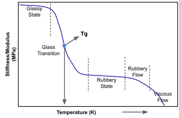
The primary reason for selecting High-Tg materials is to ensure the PCB maintains its structural integrity and electrical properties when exposed to high operating temperatures or during manufacturing processes like reflow soldering , which can momentarily exceed standard Tg values.
2. Key Features and Properties
 High-Tg and High-Temperature PCBs offer distinct advantages over their standard counterparts, primarily due to their enhanced material properties:
- Enhanced Thermal Stability:The most critical feature. A higher Tg means the material can withstand greater heat without softening, expanding excessively, or delaminating. This includes excellent decomposition temperature (Td), indicating the temperature at which the material starts to degrade.
- Improved Dimensional Stability:High-Tg materials exhibit a lower Coefficient of Thermal Expansion (CTE), especially in the Z-axis (thickness). This is vital to prevent plated through-holes (PTHs) from cracking and delamination during thermal cycling.
- Superior Mechanical Strength:These materials maintain their mechanical rigidity and resistance to delamination, even under prolonged heat exposure, ensuring the physical integrity of the board.
- Reliable Electrical Performance:While some electrical properties might slightly change with temperature, high-Tg materials are designed to maintain stable dielectric constant (Dk) and dissipation factor (Df) values across their operational temperature range, crucial for high-frequency applications.
- Chemical Resistance:Often, these materials also offer better resistance to harsh chemicals used in manufacturing processes or found in their operating environments.
3. Properties of High-Tg Materials
The selection of the right laminate material is paramount for High-Tg and High-Temperature PCBs. Common materials include advanced FR-4 variants , polyimide, and specialized ceramic-filled laminates. Key properties to consider include:
- Glass Transition Temperature (Tg):As discussed, indicates the softening point.
- Decomposition Temperature (Td ):The temperature at which the material loses 5% of its mass due to thermal decomposition. A higher Td signifies greater thermal endurance.
- Coefficient of Thermal Expansion (CTE):Measures how much a material expands per degree Celsius. Low CTE, especially in the Z-axis, is critical to prevent stress on plated through-holes.
- Dielectric Constant (Dk or Er):Influences signal speed and impedance. Stability across temperature and frequency is important.
- Dissipation Factor (Df or Tan δ):Represents signal loss in the material. Lower Df is desirable for high-frequency applications.
- Moisture Absorption :Lower moisture absorption improves reliability and prevents delamination.
Here’s a comparison of common PCB material types for high-temperature applications:
| Material Type | Typical Tg (°C) | Typical Td (°C) | Z-axis CTE (ppm/°C) | Key Characteristics | Common Applications |
| Standard FR-4 | 130-140 | 300-320 | 50-60 (below Tg), 250-3 50 (above Tg) | Cost-effective, good all-rounder for general use. Not suitable for extreme temps. | Consumer electronics, low-cost devices |
| High-Tg FR-4 | 170-180+ | 340-360+ | 40-50 (below Tg), 180-25 0 (above Tg) | Improved thermal stability, higher reliability in elevated temp environments. | Automotive, industrial controls, high-power applications |
| Polyimide | 250+ | 380-400+ | 40-50 (below Tg), 150-200 (above Tg) | Excellent thermal endurance , flexible options available, high reliability. | Aerospace, military, downhole drilling, medical implants |
| BT Epoxy (Bismaleimide-Triazine) | 180-220 | 350-370 | 45-55 (below Tg), 180-280 (above Tg) | Good thermal stability , excellent CAF resistance, often used in IC substrates. | Server boards, high-performance computing, RF applications |
| Ceramic-Filled Laminates | N/A (Ther moset) | 390-400+ | 10-20 | Extremely low CTE, very high thermal conductivity, excellent high-frequency performance. | RF/Mic rowave, power amplifiers, automotive radar |
4. Design Considerations for High-Temperature PCB Applications
Designing PCBs for high-temperature applications goes beyond simply choosing High-Tg materials. Thoughtful design practices are crucial for optimal thermal management and long-term reliability.
4.1 Layer Stack-up Optimization
- Symmetric Stack-up:A balanced stack-up helps prevent warping and twisting caused by uneven thermal expansion during manufacturing and operation.
- Copper Distribution:Distribute copper layers evenly across the board to aid in heat spreading and prevent hot spots.
- Core Thickness:Th icker cores can offer better mechanical stability and some thermal mass.
4.2 Trace Width and Spacing
- Current Carrying Capacity:High temperatures reduce the current-carrying capacity of traces. Design traces wider and thicker than standard calculations might suggest for the expected current and maximum operating temperature.
- Thermal Relief:Implement thermal reliefs on pads connected to large copper planes to prevent heat sinking during soldering and ensure proper solder joint formation.
4.3 Component Placement and Orientation
- Heat-Generating Components:Isolate high-power, heat-generating components (e.g., power ICs, MOSFETs) from sensitive components.
- Even Distribution:Distribute heat-generating components as evenly as possible to avoid localized hot spots.
- Airflow:Consider the orientation of components relative to potential airflow paths for better convection cooling.
4.4 Thermal Vias and Heat Spreading
- Via Fills:Use an array of thermal vias, often filled with thermally conductive epoxy or copper, directly under heat-generating components to transfer heat to internal copper planes or heat sinks.
- Heavy Copper:Incorporate heavy copper layers (2 oz, 3 oz, or more) to act as internal heat spreaders, efficiently distributing heat across the board.
4.5 Ground and Power Planes
- Large ground and power planes serve as excellent heat sinks, spreading thermal energy away from components.
5. Heat Transfer and Thermal Management Strategies
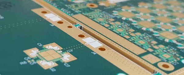
Effective thermal management is critical for the long-term reliability and performance of High-Temperature PCBs. Heat transfer in PCBs primarily occurs through conduction, convection, and radiation.
5.1 Conduction
- Within the PCB:Heat conducts through the copper traces, planes, and the laminate material itself. Heavy copper and thermal vias enhance internal conduction.
- To External Devices:Heat conducts from components to heat sinks via thermal interface materials.
5.2 Convection
- Heat is transferred from the PCB surface to the surrounding air or fluid. This can be natural convection (passive airflow) or forced convection (fans , blowers).
5.3 Radiation
- At very high temperatures, thermal radiation becomes a significant mode of heat transfer from hot surfaces.
5.4 Thermal Management Strategies for High-Tg PCBs
- Thermal Vias:As mentioned, these small, plated holes under components provide a direct thermal path to copper planes or external heat sinks.
- Heavy Copper Layers:Using thicker copper (e. g., 2 oz, 3 oz, or even higher) for power/ground planes and signal traces significantly improves heat spreading and reduces thermal resistance.
- Internal Copper Planes:Dedicated ground and power planes act as large internal heat sinks, distributing heat laterally.
- Heat Sinks:External metallic structures attached to high-power components or the PCB itself to dissipate heat into the ambient environment, often aided by fans.
- Thermal Interface Materials (TIMs):Pastes, pads, or adhesives used between a heat-generating component and a heat sink to minimize thermal resistance.
- Metal Core PCBs (MCPCBs):For extreme power dissipation, these PCBs use a metal base (e.g., aluminum) to conduct heat away from components more efficiently than traditional laminates.
- Liquid Cooling:In very high-power applications, specialized liquid cooling systems may be integrated.
- Rework and Repair:R eworking components on High-Tg boards requires specialized tools and techniques to apply heat precisely without damaging the surrounding laminate or other components.
6. Manufacturing Considerations for High-Tg PCBs
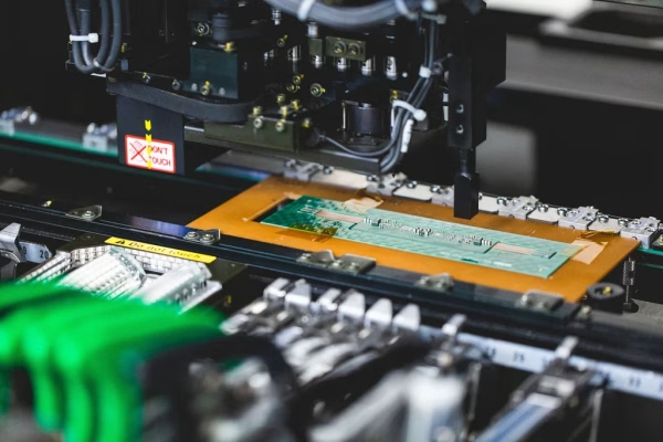
Manufacturing High-Tg PCBs presents specific challenges that require adjustments to standard fabrication processes:
- Drilling:High-Tg materials are often harder and more abrasive than standard FR-4, leading to increased drill bit wear. Optimized drill speeds, feed rates, and specialized drill bits are necessary to maintain hole quality and tool life.
- Lamination:The lamination process requires precise control over temperature and pressure cycles . The higher Tg means the material requires more heat to flow and cure properly, but excessive heat can cause material degradation.
- Etching:Standard etching processes generally work well, but material composition might slightly influence etch rates .
- Plating:Ensuring good adhesion of copper plating within through-holes is crucial, especially given the material’s higher thermal stability. Pre-treatment steps may be adjusted.
- Quality Control and Testing:More rigorous testing, including thermal cycling tests and thermal shock tests, is performed to ensure the boards meet the required reliability standards for high-temperature environments.
7. Assembly Considerations for High-Temperature PCBs
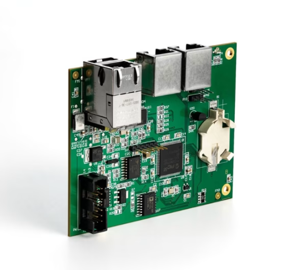
The assembly process for High-Tg and High-Temperature PCBs requires careful attention to detail , as the materials’ properties influence soldering and other operations.
- Solder Paste Selection:Use high-temperature solder pastes with appropriate melting points, especially if the operating temperature approaches the melting point of standard lead -free solders (e.g., SAC305 melts around 217°C). High-reliability alloys or epoxies might be considered.
- Reflow Profiles:High-Tg lamin ates can typically withstand higher peak reflow temperatures and longer dwell times above liquidus without damage. However, careful profiling is still essential to prevent thermal shock to components and ensure proper solder joint formation without overheating.
- Controlled Ramp Rates:Slower ramp-up and cool-down rates during reflow soldering can help minimize thermal stress on the PCB and components, reducing the risk of warpage or delamination.
- Moisture Sensitivity Levels (MSL):High-Tg laminates can still absorb moisture, which can lead to “popcorning” during reflow. Proper baking and handling according to MSL guidelines are critical.
8. Key Applications for High-Tg PCBs
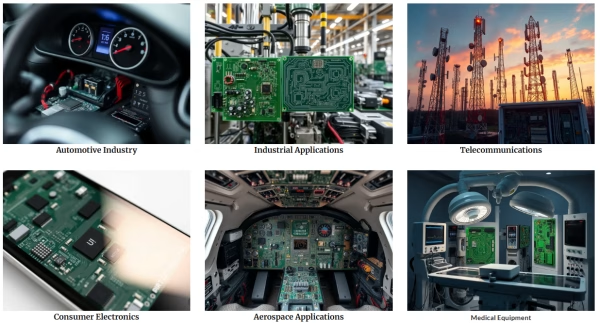
High-Tg and High-Temperature PCBs are vital for a wide array of demanding applications:
- Automotive Electronics:Engine control units (ECUs), LED lighting systems, and sensor modules operating in engine compartments.
- Aerospace and Defense:Avionics, control systems, and communication equipment subjected to extreme thermal variations.
- Industrial Controls:Power supplies, motor controllers, and automation systems in harsh factory environments.
- High-Power LED Lighting:Boards for LED arrays where heat dissipation is critical for LED longevity.
- Oil & Gas:Downhole drilling equipment and sensors exposed to high temperatures and pressures.
- Medical Devices:Implants and diagnostic equipment that require high reliability and resistance to sterilization temperatures.
9.FAQs
The main difference is the Glass Transition Temperature (Tg). High-Tg PCBs have a Tg typically above 150°C (compared to 130-140°C for standard FR-4), allowing them to maintain structural integrity and electrical properties at higher operating temperatures without softening or delaminating.
A low Z-axis Coefficient of Thermal Expansion (CTE) is crucial because it minimizes the expansion of the PCB material in its thickness direction when heated. This prevents stress on the plated through-holes (PTHs), reducing the risk of cracking in the copper plating and ensuring reliable electrical connections.
While some High-Tg PCBs can tolerate standard lead-free solder reflow profiles, it’s often advisable to use solder pastes specifically designed for higher temperatures or to carefully optimize the reflow profile. For very high operating temperatures, specialized high-melting-point solders or conductive epoxies might be necessary.
Thermal vias are small, plated holes typically placed directly under heat-generating components. They act as conductive pathways, transferring heat efficiently from the component’s pad to internal copper planes or external heat sinks , thus preventing localized hot spots and improving overall thermal management.
10.Summary
High-Tg and High-Temperature PCBs are essential components for modern electronics operating in challenging thermal environments. Their enhanced thermal stability, improved mechanical strength, and reliable electrical performance are direct results of specialized material selection (such as high-Tg FR-4, polyimide, and BT epoxy) and meticulous design considerations. From optimizing layer stack-ups and trace geometries to implementing robust thermal management strategies like heavy copper and thermal vias, every aspect of these PCBs is engineered for resilience. Manufacturing and assembly processes also require specific adjustments to accommodate the unique properties of these advanced materials.








