Flexible PCB Assembly Guide: Files, Support & Testing
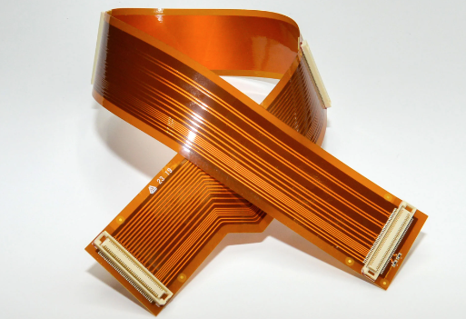
Table of Content
- What is flexible PCB assembly?
- 1. Define the circuit construction and mechanical use.
- 2. Keep the quote files on one revision.
- 3. Plan support, handling and soldering for the actual circuit.
- 4. Agree on inspection and functional test coverage.
- 5. Compare a complete project quote.
- Request a flex PCBA build review.
- Flexible PCB assembly questions.
FLEX PCBA · ENGINEERING AND QUOTE PREPARATION
What is flexible PCB assembly?
Flexible PCB assembly mounts and solders components onto a flexible circuit. A useful build review combines the circuit construction, BOM, placement data, bend requirements, mechanical support and agreed tests. Define where the circuit can move and where populated areas need support before approving production.
For a complete build, you can ask OrinewPCB to review flexible-circuit fabrication, component sourcing and assembly together. Start with your flexible PCB assembly requirements, sample quantity and any expected next batch.
1. Define the circuit construction and mechanical use.
Specify the material grade, layer construction, thickness, coverlay, stiffeners and finish in your fabrication and mechanical files. Flexible circuits formed during installation and circuits that flex repeatedly in service have different mechanical demands.
Mark the bend regions, installed shape and intended motion. Include the required radius or mechanical envelope where known. The stack-up, conductor layout and surrounding mechanical features need a review against those requirements.

Identify supported areas.
Draw the stiffener material, thickness and outline. Include connector insertion requirements and any critical dimensions. A stiffener provides local mechanical support; rigid-flex combines rigid and flexible circuit sections in its construction.
Read about flex circuit stiffeners · Review rigid-flex assembly requirements
2. Keep the quote files on one revision.
A complete project package helps the assembly team connect your electrical design, mechanical use and purchasing requirements. Identify missing files clearly rather than assuming the team has the latest version.
- Fabrication data: Gerber and drill files, outline, stack-up, finish and manufacturing notes.
- Mechanical drawing: bend regions, stiffeners, installed shape, connector areas and critical dimensions.
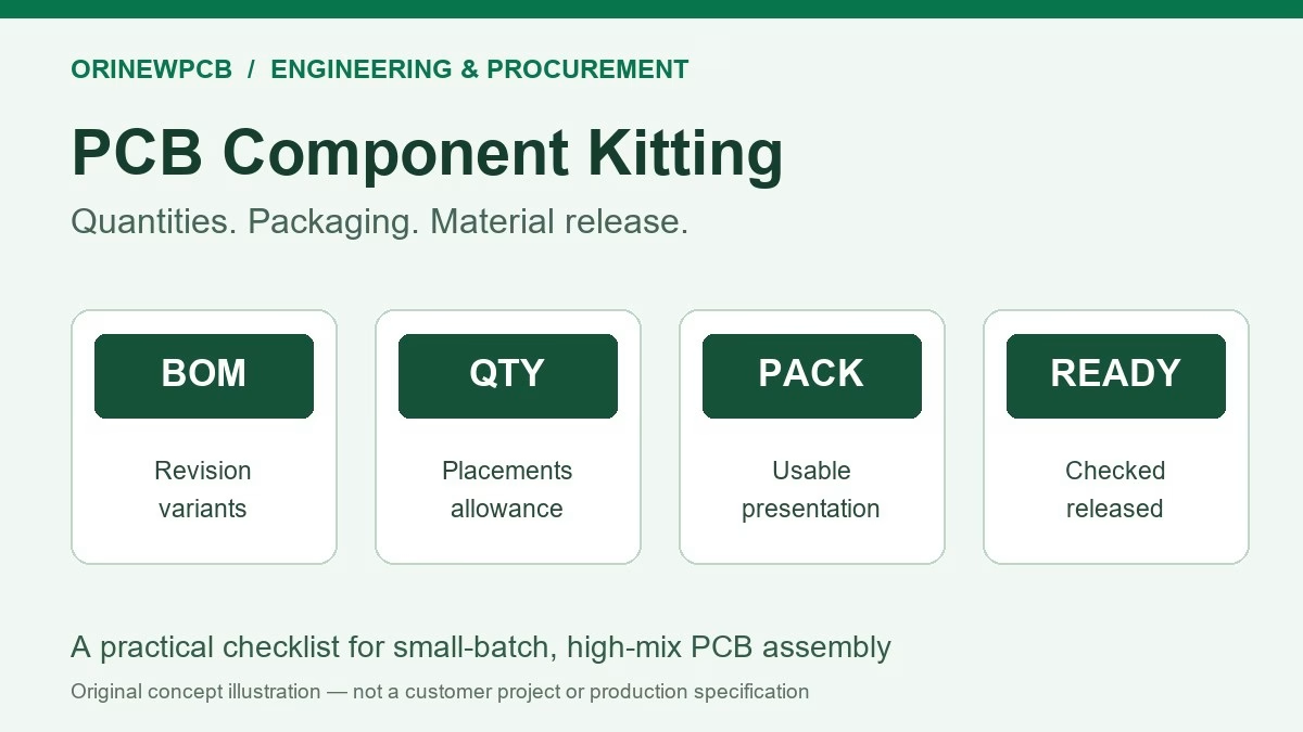
- BOM: manufacturer, full part number, reference designator, quantity per circuit and do-not-fit positions.
- Placement data: coordinates, rotation, origin and component side; include assembly drawings.
- Build requirements: sample and batch quantity, material responsibilities, target date and destination.
- Test package: required checks, firmware, programming instructions, fixture needs and pass/fail criteria.
Flag approved alternatives and parts that must not be changed. Proposed substitutions require a design review and your approval; a similar part description alone does not establish equivalence.
3. Plan support, handling and soldering for the actual circuit.
The circuit needs stable support where the manufacturing process requires accurate positioning. Show populated regions, panel features, fragile tails and areas that can contact a carrier or fixture.
Material handling
Review storage, moisture handling and any conditioning requirements against the material and component documentation. Temperature and time are determined for the actual construction.
Placement and soldering
Confirm component orientation, supported areas and thermal requirements. For components on both sides, include both placement views and discuss the assembly sequence.
Post-assembly handling
Define any forming, connector insertion, packaging and transport requirements. Protect populated areas and flexible tails according to the approved mechanical use.
4. Agree on inspection and functional test coverage.
Visual inspection, AOI, X-ray, electrical checks and functional tests answer different questions. Select the coverage that fits the design and project requirements, and record it in the quote.
- Assembly inspection: discuss placement, polarity and solder-joint checks, including hidden-joint inspection where required.
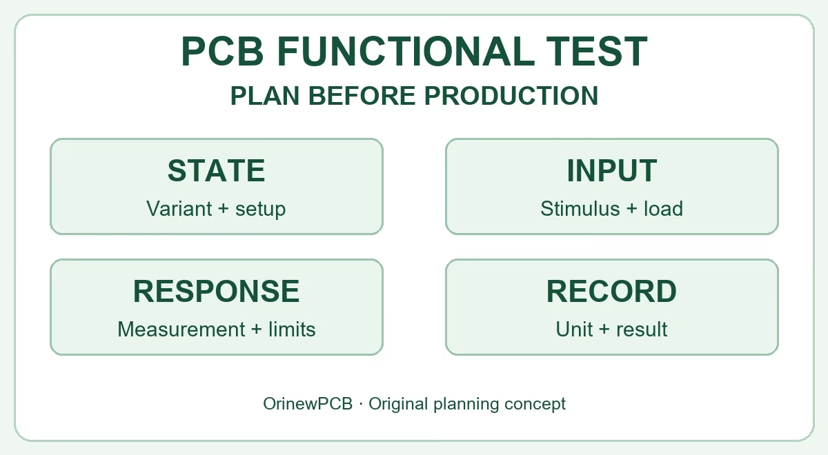
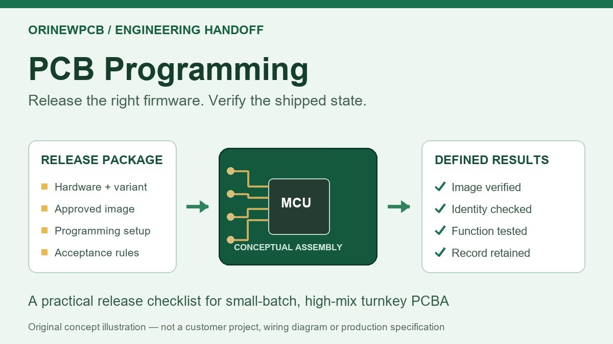
- Programming and functional tests: provide firmware, procedure, fixture requirements and pass/fail limits.
- Mechanical or bend validation: identify it separately when the application requires it, with the agreed method and acceptance criteria.
- Fixture access: show connectors, test points and supported contact areas.
Inspection results cannot establish every aspect of product performance. Product-specific functional and mechanical validation needs a defined scope.
5. Compare a complete project quote.
Construction, material availability, panelization, stiffeners, component sourcing, assembly support and test preparation affect the quote. Review setup or fixture costs separately from recurring production costs.
Send the first-build quantity and the planned next batch. A sample approval should identify the board and BOM revision, test scope and any changes required before repeat production.
Material availability and the reviewed manufacturing plan determine the practical schedule. Confirm changes in sourcing, construction or test preparation before relying on a delivery date.
Understand PCBA quote cost factors · Use the prototype-to-production release checklist
Request a flex PCBA build review.
Send your circuit files, BOM, mechanical drawing and quantity when available. For a one-stop build, specify full turnkey support covering the agreed fabrication, component sourcing and assembly.
Suggested request: “Full turnkey flex PCBA; [sample quantity] and [next batch quantity]; [target date and destination]; bend/stiffener drawing attached; [programming or testing requirements].”
Files can follow by email. An initial request does not approve purchasing or production.
Flexible PCB assembly questions.
Does a flex circuit automatically support repeated bending?
No. Repeated movement requires a construction and mechanical design suited to the intended service conditions. Identify those requirements in the drawing and agree on any mechanical validation needed.
Can I request a quote before my placement file is ready?
Yes. Describe the available files and missing information. Complete and consistent assembly data may be needed for a final manufacturing quote.
Can I supply selected components?
Yes. Identify the supplied parts, quantities, condition and expected arrival dates so the partial turnkey responsibilities can be reviewed.
Is functional testing included automatically?
Confirm the test scope in the quote. A functional test requires a procedure, pass/fail criteria and any firmware or fixture arrangements that the build needs.
Related Posts
ORINEWPCB · PROJECT SUPPORT
Contact Us
Discuss your PCB assembly project with our team.
FREE QUOTE
Plan your turnkey PCBA build.
Share your quantity and requirements. Add Gerber files and a BOM when ready.
Files are optional for an initial discussion. Include any assembly, sourcing or testing requirements in your message.