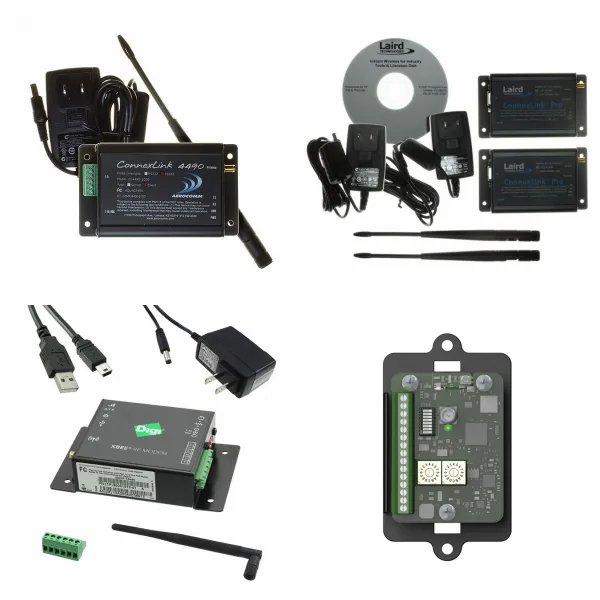
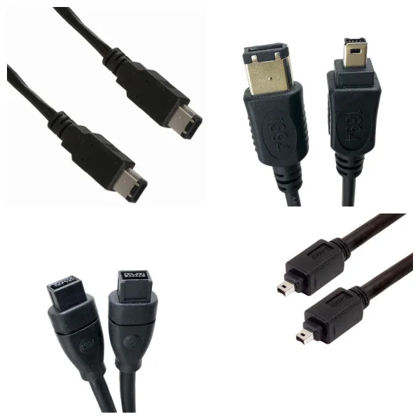
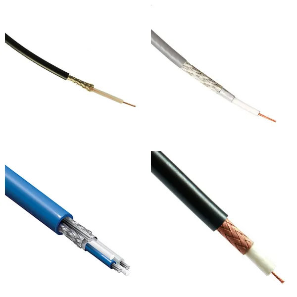
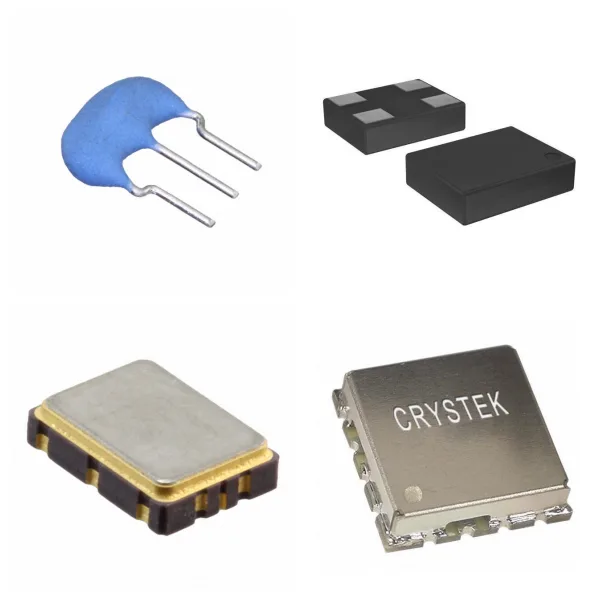
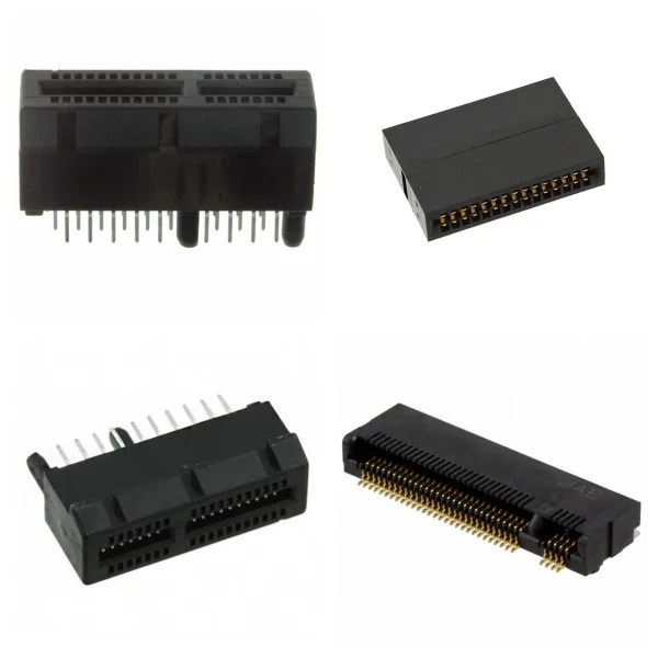
<h1> RF and Wireless </h1> <h2> 1. Radio Frequency (RF) Overview </h2> <p> <strong>1) Definition and Frequency Band</strong>: Radio Frequency refers to electromagnetic waves in the 300kHz-300GHz frequency band, which has high-frequency alternating characteristics and is the basic carrier of wireless signal transmission. </p> <p> <strong>2) Key Components</strong>: </p> <p> <strong>Passive devices</strong>: including inductors, capacitors, directional couplers and waveguides, etc., are used for signal matching, filtering, and power distribution. </p> <p> <strong>Active devices</strong>: such as microwave power amplifiers, diodes, and transistors, which undertake signal amplification, modulation, and demodulation functions. </p> <p> <strong>Connector</strong>: RF connectors (such as SMA and BNC) are used as electrical interfaces of transmission lines to ensure low-loss transmission of high-frequency signals. </p> <h2> 2. What is the Classification of Wireless Communication Technologies? </h2> <h3> 1)Short-Range Communication </h3> <p> <strong>Bluetooth</strong>: Based on the IEEE 802.15.1 standard, it uses the 2.4GHz ISM frequency band and a master-slave structure, which is suitable for low-power device interconnection. </p> <p> <strong>Wi-F</strong><strong>i</strong>: Follows IEEE 802.11 protocol, supports 2.4GHz/5GHz frequency bands, provides high-speed LAN access, and requires optimization of microstrip or coplanar waveguide transmission line impedance during design. </p> <p> <strong>RF</strong>: Such as 315MHz/433MHz frequency bands, used for remote controls and access control systems, with low transmission rates but low costs and complexity. </p> <h3> 2)Wide Area Communications </h3> <p> <strong>Mobile Network (4G/5G)</strong>: Integrates cellular technology and WLAN to achieve high-bandwidth, low-latency data transmission. </p> <p> <strong>LPWAN technology</strong>: Such as NB-IoT, designed specifically for the Internet of Things, covering long-distance, low-power scenarios. </p> <h2> 3. What is RF and Wireless Used for? </h2> <p> <strong>RF Module</strong>: Integrates high-frequency transceiver circuits, supports 1M-2Mbps rates, and is used in vehicle monitoring, industrial data collection, and smart homes. </p> <p> <strong>Antenna design</strong>: It is necessary to consider PCB stacking (such as L2 as RF reference ground in the four-layer board), routing continuity to avoid signal reflection, and matching network optimization (such as parallel capacitors and series inductors) to improve efficiency. </p> <h2> 4. How to Evaluate RF and Wireless? </h2> <p> <strong>Performance indicators</strong>: Including transmission power, frequency error, adjacent channel leakage ratio (ACLR) and receiving sensitivity, etc., which need to be tested by conduction and radiation methods. </p> <p> <strong>International certification</strong>: Such as FCC (USA), CE (EU), and TELEC (Japan), to ensure that the equipment complies with electromagnetic compatibility and RF specifications. </p> <h2> 5. What is the Development Trend of RF and Wireless? </h2> <p> <strong>High frequency</strong>: Expand to millimeter wave (30-300GHz) to meet 5G/6G requirements. </p> <p> <strong>Integration</strong>: SOC (system on chip) integrates RF front-end and baseband processing to reduce power consumption and volume. </p>
<h1> Resistors </h1> <h2> 1. Resistors Overview </h2> <h3> 1)Basic Concepts </h3> <p> The resistor is a passive component used to limit the flow of current in a circuit. It realizes the current limiting function by converting electrical energy into heat energy and is an energy-consuming component. Its resistance is determined by factors such as material, temperature, length, and cross-sectional area. </p> <h3> 2)Core Function </h3> <p> Voltage division and current division: Ensure stable operation of various parts of the circuit by adjusting voltage or current distribution. </p> <p> Current limiting and protection: Prevent current overload from damaging sensitive components. </p> <h2> 2. What are the Types of Resistors? </h2> <h3> 1)Classification by resistance characteristics </h3> <p> <strong>Fixed resistors</strong>: The resistance value cannot be adjusted, suitable for stable circuit design. </p> <p> <strong>Adjustable resistors</strong>: Such as potentiometers, which change the resistance value by sliding contacts and are used to accurately adjust circuit parameters. </p> <h3> 2)Classification by materials and processes </h3> <p> <strong>Wire-wound resistors</strong>: High precision, high-temperature resistance, suitable for high-power scenarios. </p> <p> <strong>Metal film/carbon film resistors</strong>: Low cost, low noise, widely used in general circuits. </p> <p> <strong>Chip resistor</strong>: Surface mount technology (SMT), small size, suitable for automated production. </p> <h3> 3)Special function resistor </h3> <p> <strong>Thermistor</strong>: Resistance changes with temperature, used for temperature sensing. </p> <p> <strong>Varistor</strong>: Voltage-sensitive, used for overvoltage protection. </p> <p> <strong>Photoresistor</strong>: Light intensity controls resistance, used in light control equipment. </p> <h2> 3. What are the Key Parameters of Resistors? </h2> <p> <strong>Resistance (Ω)</strong>: The Unit is ohm, marked by a color ring (plug-in resistor) or digital code (chip resistor). </p> <p> <strong>Power (W)</strong>: Maximum power that the resistor can withstand, which needs to match the circuit requirements to avoid overheating. </p> <p> <strong>Temperature coefficient</strong>: Measures the stability of resistance with temperature changes, and low-temperature coefficient is suitable for precision circuits. </p> <h2> 4. What are Resistors Used for? </h2> <p> <strong>General circuit</strong>: Basic functions such as voltage division, current limiting, and filtering. </p> <p> <strong>Precision instruments</strong>: Such as medical equipment and communication systems, which rely on high-precision resistors to ensure signal stability. </p> <p> <strong>Protection circuit</strong>: Varistors are used for lightning protection, and thermistors are used for overheating protection. </p> <p> <strong>Sensors</strong>: Photosensitive and thermistors play a key role in environmental monitoring. </p> <h2> 5. What is the Industrial chain and production of Resistors? </h2> <p> <strong>Production process</strong>: including thick film/thin film technology (chip resistors), winding process (high-power resistors), etc. </p> <p> <strong>Major manufacturers</strong>: such as Yageo and Fenghua Hi-Tech, occupy an important share of the global passive component market. </p> <h2> 6. Resistors FAQs </h2> <h3> 1) How to calculate the total resistance of resistors in series and parallel? </h3> <p> <strong>Series</strong>: The total resistance is equal to the sum of the resistances of each resistor, that is, Rtotal=R1+R2+⋯+Rn. </p> <p> <strong>Parallel</strong>: The reciprocal of the total resistance is equal to the sum of the reciprocals of each resistor, that is, Rtotal/1=R1 /1+R2/1+⋯+Rn/1. </p> <h3> 2) Can chip resistors be used above the rated temperature? </h3> <p> It is not recommended to use it above the rated temperature for a long time, which may cause performance degradation or damage. Please refer to the manufacturer's technical documents to evaluate the use conditions. </p> <h3> 3) What are the main functions of resistors in circuits? </h3> <p> Limiting current, voltage division, protecting sensitive components (such as LEDs), signal conditioning, etc. </p> <h3> 4)How to choose the rated power of resistors? </h3> <p> It needs to be selected based on the actual power consumption (P=I2R), ensuring that the rated power is greater than the actual power to avoid overheating failure while considering the influence of ambient temperature. </p> <h3> 5) Why must resistors be connected in series in LED circuits? </h3> <p> Current limiting is used to prevent LEDs from burning out due to excessive current. In typical applications, the resistance value needs to be calculated based on the LED voltage and the power supply voltage. </p> <h2> 6) What are the failure modes of resistors? </h2> <p> Common failures include overheating, resistance drift (caused by temperature or aging), and mechanical damage (such as package cracking). </p> <h2> 7. Summary </h2> <p> Resistors, as the basic components of electronic circuits, have a variety of types and parameter designs that meet a wide range of needs from consumer electronics to industrial equipment. </p> <p> In the future, with the trend of intelligence and precision, high reliability, miniaturization, and functional integration will become the core direction of the development of resistor technology. </p>
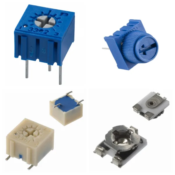
<h1> Potentiometers, Variable Resistors </h1> <h2> 1. Potentiometers and Variable Resistors Overview </h2> <p> <strong>Potentiometer</strong>: A resistor element with three terminals and adjustable resistance. The resistance value is changed by sliding contacts to achieve voltage division or current limiting functions. Its core principle is to change the length of the current path or the contact area by adjusting the contact position, thereby changing the output resistance. </p> <p> <strong>Variable Resistors</strong>: In a broad sense, it includes potentiometers, but in a narrow sense, it refers to variable resistors with only two effective terminals (such as fine-tuning resistors). The resistance value is changed by adjusting the mechanical structure, and it is often used for circuit calibration or debugging. </p> <h2> 2. What is the Structure and Working Principle of Potentiometers? </h2> <p> <strong>Structure</strong>: The potentiometer consists of a resistor element (such as carbon film, and wire-wound resistor) and a sliding contact. The two ends of the resistor element are fixed terminals, and the sliding end (brush) changes the contact point position by rotation or linear movement. </p> <p> <strong>Voltage division principle</strong>: The input voltage is applied to the two ends of the resistor element, and the voltage output between the sliding end and any fixed end is proportional to the contact position, realizing the voltage division function. </p> <h2> 3. What are the Common Types of Potentiometers? </h2> <h3> 1)By adjustment method: </h3> <p> <strong>Rotary potentiometer</strong>: Adjusted by knob, widely used in volume control, brightness adjustment, etc. </p> <p> <strong>Linear (sliding) potentiometer</strong>: Adjusted by linear sliding, suitable for scenarios requiring linear response (such as dimmers). </p> <p> <strong>Trimmer</strong>: Miniaturized design requires tool adjustment and is used for circuit debugging or calibration. </p> <h3> 2)By material and power: </h3> <p> <strong>Carbon film/ceramic film potentiometer</strong>: Low cost, suitable for low power scenarios. </p> <p> <strong>Wire wound potentiometer</strong>: High power, high precision, used for industrial control. </p> <h2> 4. What are Potentiometers Used for? </h2> <p> <strong>Voltage division and signal adjustment</strong>: Audio equipment volume control, sensor signal adjustment. </p> <p> <strong>Power control</strong>: Light dimmer, motor speed adjustment (pay attention to power limit). </p> <p> <strong>Calibration and debugging</strong>: Trimmer resistors are used for precise adjustment of circuit parameters (such as bias voltage). </p> <h2> 5. What are the Key Parameters of Potentiometers? </h2> <p> <strong>Resistance range</strong>: Commonly from a few hundred ohms to megohms, selected according to the application. </p> <p> <strong>Power rating</strong>: Determines the maximum power consumption that can be tolerated (such as 0.1W to 5W). </p> <p> <strong>Linearity</strong>: The corresponding relationship between the change in resistance and the movement of the contact, affects the control accuracy. </p> <p> <strong>Mechanical life</strong>: The number of rotations or slides (usually tens of thousands of times). </p> <h2> 6. What is the Special Function Design of Potentiometers? </h2> <p> <strong>Attached switch</strong>: Some potentiometers integrate power switches, which are common in volume control knobs (triggered off when the contact is adjusted to the minimum resistance value). </p> <p> <strong>Multi-gang potentiometer</strong>: Multiple resistance units are linked, used in stereo audio equipment. </p> <h2> 7. Typical Brands for Potentiometers </h2> <p> BOURNS </p> <p> VISHAY </p> <p> TE </p> <p> ALPHA </p> <p> Panasonic </p> <p> Amphenol </p> <h2> 8. Potentiometers FAQs </h2> <h3> 1) What is the difference between a potentiometer and a variable resistor? </h3> <p> <strong>Potentiometer</strong>: Usually used as a three-terminal component, it outputs a voltage proportional to the contact position through the voltage division principle. </p> <p> <strong>Variable Resistor</strong>: Generally used as a two-terminal component, it only limits the current by adjusting the resistance value and has no voltage division function. </p> <h3> 2) What are the advantages of digital potentiometers? </h3> <p> It can be adjusted by a microprocessor or digital signal to support automatic control. </p> <p> Some models integrate non-volatile memory to retain the settings after power failure. </p> <p> It is small and high in precision, suitable for highly integrated circuits. </p> <h3> 3) What are the common faults and detection methods of potentiometers? </h3> <p> <strong>Poor Contact</strong>: It is manifested as a jump in the output signal. A multimeter can be used to detect whether the resistance value changes continuously. </p> <p> <strong>Mechanical Wear</strong>: Noise occurs when rotating or sliding, and the potentiometer needs to be replaced. </p> <p> <strong>Detection Steps</strong>: Measure whether the total resistance of the two ends meets the nominal value, and check whether the resistance between the sliding end and the fixed end changes linearly with the adjustment. </p> <h3> 4) Which special potentiometers have additional functions? </h3> <p> <strong>Potentiometer with switch</strong>: The switch can be triggered when rotating or sliding to the extreme position, which is often used in the integrated design of power switches and volume adjustment (such as old radios). </p> <p> <strong>Multi-gang potentiometer</strong>: Multiple potentiometers share the same adjustment axis, which is used to synchronously control multiple signals (such as stereo audio balance adjustment). </p> <h3> 5) What role does the potentiometer play in analog-to-digital conversion? </h3> <p> In the analog signal acquisition system, the potentiometer can be used as a voltage divider to provide a reference voltage and cooperate with the analog-to-digital converter (ADC) to convert analog signals (such as position and brightness) into digital signals. </p> <h2> Summary </h2> <p> Potentiometers and variable resistors adjust resistance values mechanically or digitally. They are core components of analog circuit control and are widely used in consumer electronics, industrial equipment, and debugging scenarios. Their selection needs to comprehensively consider resistance range, power, accuracy, and usage environment. </p>
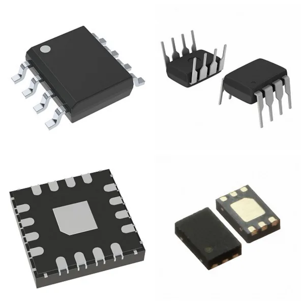
<h1> Integrated Circuits (ICs) </h1> <h2> 1. Integrated Circuits (ICs) Overview </h2> <p> Integrated Circuits is a microelectronic device that integrates electronic components such as transistors, resistors, capacitors, inductors, etc. on semiconductor chips (such as silicon or gallium arsenide) or dielectric substrates through specific processes. All components form a whole structure, with the characteristics of miniaturization, low power consumption, high reliability, etc., and are represented by "IC" in the circuit. </p> <h2> 2. What are the Types of Integrated Circuits (ICs)? </h2> <p> According to functions and application scenarios, ICs are mainly divided into the following categories: </p> <p> <strong>Analog integrated circuits</strong>: Processing continuous signals, such as operational amplifiers and sensor signal conditioning chips. </p> <p> <strong>Digital integrated circuits</strong>: Processing discrete digital signals, including logic gates, microprocessors, memories, etc. </p> <p> <strong>Mixed-signal integrated circuits</strong>: Combining analog and digital functions, such as analog-to-digital converters (ADCs) and digital-to-analog converters (DACs). </p> <p> <strong>Power ICs</strong>: Focusing on power management and driving, such as power management chips (PMICs) and driver chips (Driver ICs), are widely used in smartphones, automobiles, and industrial equipment. </p> <p> <strong>RF/Microwave ICs</strong>: used in high-frequency communication systems, such as 5G RF chips and microwave filters. </p> <h2> 3. What are Integrated Circuits (ICs) Used for? </h2> <p> <strong>Communication Technology</strong>: Processors and RF chips in smartphones, and high-speed data transmission modules for 5G base stations. </p> <p> <strong>Medical Equipment</strong>: Low-power control chips for wearable health monitoring devices (such as smartwatches) and implantable devices (such as pacemakers). </p> <p> <strong>Automotive Electronics</strong>: Sensor processing chips for autonomous driving systems, vehicle-to-everything (V2X) communication modules, and battery management systems (BMS) for electric vehicles. </p> <p> <strong>Computers and Consumer Electronics</strong>: High-performance computing chips such as CPUs and GPUs, as well as control units in home appliances. </p> <p> <strong>Industry and Internet of Things</strong>: Low-power chips for industrial automation controllers and Internet of Things nodes. </p> <h2> 4. What are the Main Features of Integrated Circuits (ICs)? </h2> <p> <strong>High Integration</strong>: Nanoscale component density is achieved through processes such as photolithography, and performance is continuously improved in accordance with Moore's Law. </p> <p> <strong>Low-power Design</strong>: CMOS technology is used to reduce energy consumption, suitable for mobile devices and wearable technology. </p> <p> <strong>Reliability</strong>: Packaging technology (such as QFN, and BGA) improves anti-interference ability and environmental adaptability. </p> <h2> 5. What are the Manufacturing Process of Integrated Circuits (ICs)? </h2> <p> <strong>Design and verification</strong>: Circuit design and simulation are completed through EDA tools. </p> <p> <strong>Wafer processing</strong>: Circuit structure is formed on silicon wafers through deposition, lithography, etching, and other processes. </p> <p> <strong>Packaging test</strong>: After cutting the wafer, it is packaged into independent chips, and functional and reliability tests are performed. </p> <h2> 6. What are the Industry Trends of Integrated Circuits (ICs)? </h2> <p> With the popularization of 5G, artificial intelligence and electric vehicles, the demand for high-performance, low-power ICs continues to grow. In 2024, the global power ICs market size has exceeded US$21.5 billion, and it is expected to expand further in the fields of smart driving and green energy in the future. </p> <h2> 7. Typical Brands for Integrated Circuits (ICs) </h2> <p> NXP </p> <p> DIODES </p> <p> ST </p> <p> ON </p> <p> TI </p> <h2> 8. Integrated Circuits (ICs) FAQs </h2> <h3> 1) What are the core components and materials of ICs? </h3> <p> <strong>Material</strong>: Semiconductor wafers are mainly based on silicon (Si) or germanium (Ge), with silicon being the mainstream in modern times. </p> <p> <strong>Composition</strong>: Transistors, resistors, capacitors, and interconnect wiring are integrated into semiconductor substrates through processes such as lithography, diffusion, and oxidation. </p> <h3> 2) What key technologies are involved in the manufacturing of ICs? </h3> <p> <strong>Core Processes</strong>: Oxidation, lithography, diffusion, epitaxial growth, metal evaporation, etc. </p> <p> <strong>Design Technology</strong>: Including circuit design, layout and packaging testing, etc. </p> <h3> 3) What are the Advantages of ICs over discrete component circuits? </h3> <p> <strong>Volume and Weight</strong>: Highly integrated, greatly reducing circuit size. </p> <p> <strong>Performance</strong>: Low power consumption, high reliability, and suitable for mass production. </p> <p> <strong>Cost</strong>: The cost of mass production is lower than that of discrete component combinations. </p> <h3> 4) What are the common methods for IC failure analysis? </h3> <p> <strong>Electrical Analysis</strong>: Curve tracer (CT) detects short circuits/open circuits, and parameter analyzer evaluates transistor performance. </p> <p> <strong>Optical Inspection</strong>: Infrared microscopy locates internal defects, and thermal emission microscopy (TIVA/OBIRCH) detects leakage current points. </p>
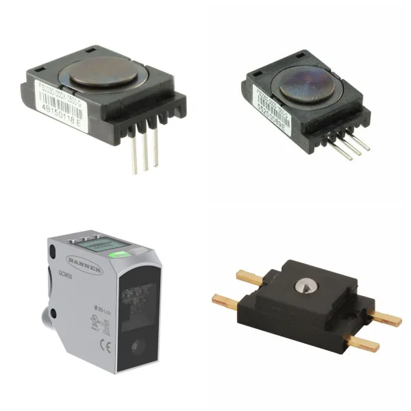
<h1> Industrial Automation and Controls </h1> <h2> 1. What are the Core Components of Industrial Automation Products? </h2> <h3> 1)Controller </h3> <p> <strong>PLC (Programmable Logic Controller)</strong>: As the "brain" of the industrial automation system, PLC implements logical operations, data processing and equipment communication through programming, replacing the traditional relay system, and has high reliability, flexibility and scalability. </p> <p> <strong>Intelligent controller</strong>: Supports complex algorithms and multi-device collaborative control, and is widely used in production lines, energy management and other scenarios. </p> <h3> 2)Sensors and actuators </h3> <p> <strong>Sensors</strong>: Including temperature, pressure, photoelectric and other types, used to monitor physical quantities in real time and convert them into electrical signals to provide data input for the system. </p> <p> <strong>Electric actuator</strong>: Drive mechanical movement through electric motors to achieve precise control of equipment such as valves and conveyor belts, support remote operation, and automated processes. </p> <h3> 3)Auxiliary components </h3> <p> <strong>Circuit breakers and relays</strong>: Ensure circuit safety, and achieve signal isolation and load control. </p> <p> <strong>Inverter and servo system</strong>: Used for motor speed regulation and precision motion control to improve production efficiency and energy consumption management. </p> <h2> 2. Where are Industrial Automation Products Used for? </h2> <p> <strong>Production line automation</strong>: Monitor parameters through sensors and adjust equipment status through PLC to ensure product quality and production efficiency. </p> <p> <strong>Energy and environmental management</strong>: Applied to pumping stations, sewage treatment, exhaust gas monitoring, and other systems to achieve remote control and energy-saving optimization. </p> <p> <strong>Intelligent manufacturing</strong>: Combined with machine vision (industrial cameras), 3D modeling, and other technologies, promote flexible manufacturing and smart factory construction. </p> <h2> 3. What are the Technical Features of Industrial Automation Products? </h2> <p> <strong>Programmability</strong>: Support flexible configuration of control logic to adapt to diverse industrial scenarios. </p> <p> <strong>High precision and reliability</strong>: Millimeter-level control is achieved through components such as encoders and gratings to ensure long-term stable operation of the system. </p> <p> <strong>System integration</strong>: Supports interconnection with MES, SCADA, and other systems to build a data-driven remote monitoring and management platform. </p> <h2> 4. What are the Frontier Trends of Industrial Automation Products? </h2> <p> <strong>Intelligent sensors</strong>: Integrate edge computing capabilities to achieve real-time data analysis and local decision-making. </p> <p> <strong>Modular design</strong>: Simplify equipment deployment and maintenance through standardized interfaces (such as communication modules). </p> <p> <strong>Green Automation</strong>: Optimize energy consumption algorithms and integrate renewable energy to promote sustainable development. </p>
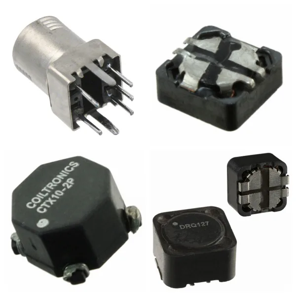
<h1> Inductors, Coils, Chokes </h1> <p> All three are essentially inductors, and the differences in their names stem from the different emphasis on design goals, structural features, and application scenarios. </p> <h2> 1. What are Inductors, Coils and Chokes? </h2> <p> Inductor: A passive component that uses the self-inductance effect as its core principle to store magnetic energy and resist current changes through the principle of electromagnetic induction. Its basic functions include filtering, oscillation, waveform transformation, and cooperating with capacitors to achieve resonant circuits. </p> <p> Coil: A multi-turn wire structure wound by enameled wire, usually as a physical implementation form of an inductor, widely used in electromagnets, transformers, radio transmitters, and other scenarios. </p> <p> Choke: A specially designed inductor that is used to suppress high-frequency AC signals (such as radio frequency interference) while allowing DC or low-frequency current to pass. Its core function is to block unnecessary AC components through high reactance. </p> <h2> 2. What are the Structural Differences between Coils and Chokes? </h2> <p> Coil: Usually a hollow or cored winding structure, the core material (such as ferrite, alloy powder core) can significantly increase the inductance value. For example, the "tank circuit" in the radio transmitter often uses a high-Q hollow coil. </p> <p> Choke: The design emphasizes high-frequency impedance characteristics, often using core materials and optimizing the winding method to reduce distributed capacitance. For example, the high-frequency noise of the switching power supply is suppressed by the choke in the power supply filter circuit. </p> <h2> 3. What are Inductors, Coils and Chokes Used for? </h2> <h3> 1)Coil: </h3> <p> Electromagnetic equipment: such as transformer windings, and relay coils. </p> <p> High-frequency circuits: such as RF matching networks, and antenna tuning. </p> <h3> 2)Choke: </h3> <p> Power supply circuit: suppress AC ripple in DC power supply. </p> <p> Signal processing: block radio frequency interference (RFI) from entering sensitive circuits. </p> <h3> 3)Inductor (general purpose): </h3> <p> Energy storage and filtering: such as energy storage elements in LC filter circuits. </p> <p> Energy conversion: such as step-up/step-down inductors in switching power supplies. </p> <h2> 4. Reasons for Naming Differences </h2> <p> Function-oriented naming: For example, "choke" emphasizes its function of suppressing AC ("Choke" means "choke"), while "coil" focuses on the physical structure description. </p> <p> Application scenario distinction: For example, "winding" is used to describe the coil in a motor or transformer, emphasizing its role in energy transmission; "bead" specifically refers to a small inductor used for high-frequency filtering. </p> <h2> 5. Typical Brands for Inductors, Coils and Chokes </h2> <p> BOURNS </p> <p> TDK </p> <p> VISHAY </p> <p> ABRACON </p> <p> Murata </p> <p> TOKO </p> <h2> 6. Inductors, Coils and Chokes FAQs </h2> <h3> 1) What are the differences between inductors, coils, and chokes? </h3> <p> Inductors are mainly used for energy storage and filtering; </p> <p> Coils refer to general components with winding structures; </p> <p> Chokes are inductors specifically used to suppress high-frequency noise, commonly found in power supplies and RF circuits. </p> <h3> 2) How do chokes achieve high-frequency signal isolation? </h3> <p> Chokes use the high-frequency impedance characteristics of inductors (XL=ωL) to allow DC and low-frequency signals to pass while blocking high-frequency interference. For example, RF chokes can limit high-frequency noise to local circuits. </p> <h3> 3) What parameters should be considered when selecting chokes? </h3> <p> Key parameters include inductance value, tolerance (such as ±20%), saturation current (such as 3.75A), DC resistance (such as 37mΩ), and self-resonant frequency (such as 65MHz). Common-mode chokes also need to consider common-mode impedance (such as 300Ω). </p> <h3> 4) How should inductors be selected in high-frequency circuit design? </h3> <p> Shielded inductors (such as Power Shielded Inductors) should be preferred to reduce electromagnetic interference; high-frequency transformers should adopt planar or ferrite core designs to optimize performance. </p> <h3> 5) In what scenarios do common-mode chokes need to be used? </h3> <p> Common-mode chokes (such as 744212510 models) are often used to suppress common-mode noise in power lines or communication lines and are suitable for EMI filtering and high-speed data transmission systems. </p> <h3> 6) What is the role of chokes in radio frequency (RF) circuits? </h3> <p> In broadband communications (such as fiber optic networks), RF chokes can isolate high-frequency interference in signal paths to ensure signal integrity. </p> <h3> 7) What are the design points of high-frequency transformers? </h3> <p> The core material (such as ferrite), winding structure, and shielding process need to be optimized to meet high-frequency efficiency and low-loss requirements. Planar transformers are widely used due to their small size and good heat dissipation. </p> <h3> 8) How does the packaging form of high-power inductors affect performance? </h3> <p> For example, SMD packaged inductors such as the IHLP1616BZET1R0M01 use molded composite cores and combine high current carrying capacity (such as 10.5A saturation current) with compact size (4.06×4.06×1.8mm). </p>
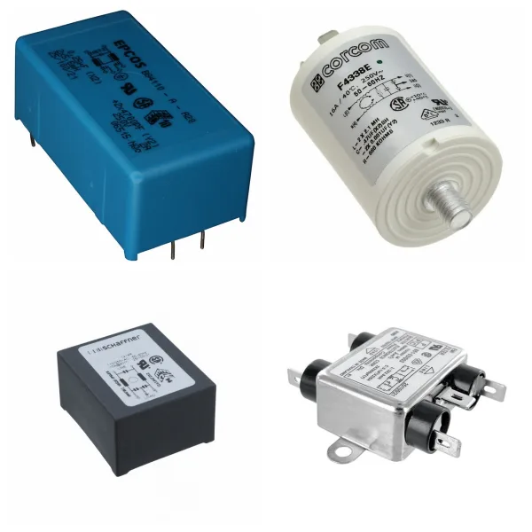
<h1> Filters </h1> <p> Filters can effectively optimize signal integrity and improve the anti-interference ability and performance of electronic systems. </p> <h2> 1. Filters Overview </h2> <p> A filter is an electronic circuit or device used for signal processing. Its core function is to improve signal quality by selectively allowing specific frequency components to pass through while suppressing or attenuating other frequency components. Its application scenarios include communication systems, power management, audio processing, and RF front-end. </p> <h2> 2. What are the Types of Filters? </h2> <h3> 1) Classification by frequency characteristics </h3> <p> Low-pass filter (LPF): allows signals below the cutoff frequency to pass through, suppresses high-frequency noise, and is often used for power supply ripple smoothing. </p> <p> High-pass filter (HPF): allows signals above the cutoff frequency to pass through, and removes low-frequency interference (such as DC offset). </p> <p> Band-pass filter (BPF): only allows signals in a specific frequency band to pass through, and is used for signal frequency division in communication systems. </p> <p> Band-stop filter (BSF): suppresses signals in a specific frequency band (such as ground reflection interference in radar systems). </p> <h3> 2) Classification by implementation method </h3> <p> Passive filter: composed of passive components such as resistors, capacitors, and inductors, with low cost, but performance limited by component parameters. </p> <p> Active filter: combined with active components such as operational amplifiers, with high gain and strong stability. </p> <p> Digital filter: processes discrete signals through algorithms (such as FIR and IIR filters) with high flexibility. </p> <h3> 3) Special Types </h3> <p> RF filter: used in wireless communication equipment (such as mobile phones and base stations) to solve the problem of interference between frequency bands. Typical types include surface acoustic wave filters (SAW) and bulk acoustic wave filters (BAW). </p> <h2> 4. What are the Key Performance Parameters of Filters? </h2> <p> Center frequency: the reference frequency of the filter passband (such as the midpoint frequency of the bandpass filter). </p> <p> Bandwidth: the frequency range allowed to pass. </p> <p> Q value (quality factor): the core indicator for measuring frequency selectivity. The higher the Q value, the stronger the frequency selectivity of the filter. </p> <p> Insertion loss: the power loss when the signal passes through the filter, which needs to be reduced as much as possible. </p> <h2> 5. Where are Filters Used for? </h2> <h3> 1) Communication system </h3> <p> Transmitter: located behind the power amplifier (PA) to filter out harmonic interference. </p> <p> Receiver: located in front of the low noise amplifier (LNA) to suppress out-of-band noise. </p> <h3> 2) Power management </h3> <p> Filter out ripple and noise in the power supply voltage and provide stable DC output. </p> <h3> 3) Biomedicine and image processing </h3> <p> A high-pass filter enhances image edge details, and a band-stop filter removes interference in specific frequency bands. </p> <h2> 6. How to Choose Filters? </h2> <p> Application scenario requirements: Base station filters require high power capacity and stability, and mobile phone filters require miniaturization and low cost. </p> <p> Environmental interference type: Select low-pass, high-pass, or band-stop type according to the noise frequency band. </p> <p> Integration process: SMT (surface mount technology) is suitable for miniaturized RF filter design. </p> <h2> 7. Typical Brands for Filters </h2> <p> SCHURTER </p> <p> MOLEX </p> <p> TDK </p> <p> Murata </p> <p> Xilinx </p> <p> TI </p> <h2> 8. Filters FAQs </h2> <h3> 1) How do filters work? </h3> <p> Filters achieve their functions through a frequency selection mechanism: they allow signals to pass with minimal attenuation in the passband, while greatly attenuating interference signals in the stopband. For example, a low-pass filter allows low-frequency signals to pass while suppressing high-frequency noise. </p> <h3> 2) What is the core difference between digital filters and analog filters? </h3> <p> Analog filters: They are composed of passive components such as resistors, capacitors, and inductors, and process continuous-time signals. They have a simple structure but low adjustment flexibility. </p> <p> Digital filters: They process discrete signals based on algorithms, have strong programmability, and are suitable for high-precision scenarios (such as IIR/FIR filters in communication systems). </p> <h3> 3) What should be noted when installing filters? </h3> <p> Wiring requirements: Reserve a "clean ground" at the cable port to avoid direct coupling between the signal ground and the filter ground. </p> <p> Electromagnetic shielding: The filter and the chassis must be reliably overlapped, and metal plates or sealing gaskets must be used to reduce RF impedance when necessary. </p> <p> Installation location: Keep as close to the interference source or sensitive equipment as possible to shorten the length of the wire after filtering. </p> <h3> 4) What are the special requirements for RF filters? </h3> <p> High-frequency performance: Need to support GHz frequency bands, such as SAW/BAW filters commonly used in 5G communications. </p> <p> Manufacturing process: Use surface acoustic wave (SAW) or bulk acoustic wave (BAW) technology to improve quality factor and temperature stability. </p> <h3> 5) What are the common causes of filter failure? </h3> <p> Environmental factors: High temperature causes capacitor capacitance drift, and high humidity causes leakage current or component corrosion. </p> <p> Overload damage: Exceeding the rated voltage/current causes inductor saturation or capacitor breakdown. </p> <p> Design defects: Failure to match system impedance causes signal reflection or abnormal insertion loss. </p>
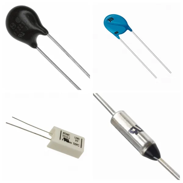
<h1> Circuit Protection </h1> <h2> 1. What are the Core functions of Circuit Protection? </h2> <p> Circuit protection is a protection mechanism for electronic devices or systems against abnormal electrical conditions, mainly including the following functions: </p> <p> Overvoltage protection: Prevent device breakdown caused by voltage transients (such as surges, and electrostatic discharge). Common protection components include varistors (MOVs) and transient suppressor diodes (TVSs). </p> <p> Overcurrent protection: Prevent thermal damage to the circuit caused by current overload by fusing or current limiting. Typical devices include self-resettable fuses (PPTCs) and traditional fuses. </p> <p> Temperature protection: Cut off the circuit by fusing or temperature-sensitive switches to prevent overheating, such as low-temperature alloy over-temperature protection components. </p> <p> Compound protection: Integrated temperature, current, and voltage multi-monitoring protection solutions (such as TFR), widely used in high-safety demand scenarios such as lithium batteries. </p> <h2> 2. What are the Main components and principles of Circuit Protection? </h2> <p> MOV (metal oxide varistor) </p> <p> Absorbs transient overvoltage energy through nonlinear resistance characteristics, suitable for power line surge protection. </p> <p> TVS (Transient Suppression Diode) </p> <p> Quick response (nanosecond level) voltage spikes, used for ESD protection of precision circuits. </p> <p> GDT (Gas Discharge Tube) </p> <p> Uses the principle of gas ionization to discharge high-energy surges, with a current resistance of 20kA, suitable for lightning protection of communication equipment. </p> <p> PPTC (Self-Resettable Fuse) </p> <p> Overcurrent protection is achieved based on temperature-resistance characteristics, and can automatically recover after the fault is removed. </p> <p> TFR (Overtemperature and Overcurrent Protection Device) </p> <p> Simultaneously monitors temperature and current anomalies, and is suitable for complex scenarios such as motors and 3C products. </p> <h2> 3. Where is Circuit Protection Used? </h2> <p> Consumer Electronics: High-speed transmission devices such as smartphones and USB interfaces rely on TVS/MOV to prevent static electricity and surge shocks. </p> <p> Automotive Electronics: The on-board power system needs to deal with the startup peak voltage, and MOV and polymer capacitors work together to ensure stability. </p> <p> Industrial Equipment: The power system uses a combination of GDT and MOV to resist lightning strikes and grid fluctuations. </p> <p> Communication base station: Ceramic gas discharge tubes (GDT) and semiconductor discharge tubes are preferred in lightning protection design. </p> <h2> 4. Technology development trend of Circuit Protection </h2> <p> High integration: A single component integrates multiple protection functions (such as TFR) to simplify the complexity of circuit design. </p> <p> Intelligent response: Combine sensors and microcontrollers to achieve dynamic threshold adjustment and improve protection accuracy. </p> <p> High-temperature material innovation: Develop high-temperature resistant alloys and polymer materials to expand the scope of application in extreme environments. </p>
<h1> Capacitors </h1> <p> Capacitors play a vital role in electronic circuits. Reasonable selection and use are the keys to ensuring circuit performance. </p> <h2> 1. Capacitors Overview </h2> <p> A capacitor is a passive electronic component consisting of two conductors (plates) close to each other and a non-conductive insulating medium (dielectric) in the middle, used to store charge and electrical energy. Its core function is to achieve temporary storage and release of energy through the charging and discharging process. </p> <p> The calculation formula of capacitance (unit: Farad, F) is: </p> <p> C=εS/4πkd </p> <p> Where ε is the dielectric constant, S is the plate area, and d is the plate spacing. </p> <h2> 2. What are the Core parameters of Capacitors? </h2> <p> <strong>Capacitance</strong>: There is a tolerance between the nominal value and the actual value, and the accuracy is usually 5%~25%. </p> <p> <strong>Rated voltage</strong>: The maximum voltage limit for the normal operation of the capacitor. </p> <p> <strong>Dissipation factor</strong>: Reflects the energy loss of the dielectric material and the equivalent series resistance (ESR). </p> <p> <strong>Temperature coefficient</strong>: The effect of temperature change on capacitance, expressed in ppm (parts per million). </p> <p> <strong>Leakage current</strong>: Determined by dielectric insulation performance, affecting long-term stability. </p> <h2> 3. What are the Types of Capacitors? </h2> <h3> 1)Differentiation by polarity: </h3> <p> <strong>Non-polar capacitors</strong>: Such as ceramic capacitors and film capacitors, which can be installed in any direction, but have a small capacity. </p> <p> <strong>Polar capacitors</strong>: Such as electrolytic capacitors (aluminum electrolytic, tantalum capacitors), which have large capacity but must strictly distinguish between positive and negative poles. </p> <h3> 2)Differentiation by structure: </h3> <p> <strong>Fixed capacitors</strong>: The capacitance is immutable. </p> <p> <strong>Variable capacitors</strong>: Change the plate spacing or area through mechanical adjustment. </p> <h2> 4.What are the Functions and Applications of Capacitors in Circuits? </h2> <p> <strong>Power supply filtering</strong>: Smooth voltage fluctuations and suppress high-frequency noise. </p> <p> <strong>Signal coupling/decoupling</strong>: Block DC components and transmit AC signals. </p> <p> <strong>Energy storage and tuning</strong>: Used in resonant circuits, energy buffering and other scenarios. </p> <p> <strong>Timing control</strong>: Cooperate with resistors to realize RC charging and discharging delay function. </p> <h2> 5. The Selection and Use Precautions of Capacitors </h2> <p> <strong>1)Voltage margin</strong>: The rated voltage must be higher than the maximum operating voltage of the circuit. </p> <p> <strong>2)Temperature adaptability</strong>: A model with a stable temperature coefficient must be selected in a high-temperature environment. </p> <p> <strong>3)Polarity judgment</strong>: <span style="font-size: 16px">The short pin or the shell mark "-" is the negative pole of the electrolytic capacitor.</span><span style="font-size: 16px">The dark end of the tantalum capacitor is the negative pole.</span><span style="font-size: 16px"></span> </p> <p> <strong>4) Installation form</strong>: The direct plug-in type is suitable for manual welding, and the SMD type is suitable for high-density PCB layout. </p> <h2> 6. Which Brands Have the Best Capacitors? </h2> <p> CHEMICON </p> <p> NICHICON </p> <p> YAGEO </p> <p> TDK </p> <p> AISHI </p> <h2> 7. Capacitors FAQs </h2> <h3> (1) How to Use Tantalum Capacitors Safely? </h3> <p> Avoid overvoltage or reverse voltage, otherwise, it may cause overheating or even short circuit; </p> <p> Some models support short-term over-temperature applications, but the derating guidelines provided by the manufacturer must be followed. </p> <h3> (2) How to Choose Capacitors in Circuit Design? </h3> <p> Low ESR capacitors (such as conductive polymer capacitors) should be preferred in power supply filtering scenarios to improve efficiency; </p> <p> High-frequency circuits need to consider the impact of ESL, and it is recommended to use multi-layer ceramic capacitors or low-inductance packages. </p> <h3> (3) How to Maintain Capacitors? </h3> <p> Tantalum capacitors usually have a long shelf life in unopened original packaging, but humid environments should be avoided to prevent oxidation. </p> <h3> (4) How to Choose the Capacitance Combination of Bypass Capacitors? </h3> <p> In high-frequency power supply design, it is usually recommended to use multiple capacitance values in parallel (such as 0.01μF and smaller capacitance capacitors) to cover the noise suppression requirements of different frequencies and add large-capacity capacitors (such as 10μF) at the power supply entrance to stabilize the power supply. </p> <h3> (5) What are the Advantages of Temperature-compensated Ceramic Capacitors? </h3> <p> Temperature-compensated ceramic capacitors (such as C0G material) have almost no capacitance change over a wide temperature range and are not affected by DC bias, making them suitable for high-precision scenarios such as high-frequency filtering and oscillation circuits. </p>
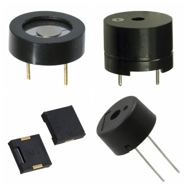
<h1> Audio Products </h1> <h2> 1. What are the Main Types of Audio Products? </h2> <h3> 1) Speaker </h3> <p> <strong>Function</strong>: Converts audio electrical signals into sound energy output, and is the core component of the audio system. </p> <p> <strong>Technical features</strong>: </p> <p> Uses a pure piston drive design, combined with aluminum and damping materials to reduce distortion. </p> <p> Sensitivity, frequency response, and directional characteristics directly affect the sound quality. </p> <h3> 2)Microphone </h3> <p> <strong>Types</strong>: Including capacitive (ECM, MEMS), dynamic, piezoelectric, etc. </p> <p> <strong>Application</strong>: Voice interaction, active noise reduction and recording scenarios, MEMS microphones have become the first choice for consumer devices due to their high consistency. </p> <p> <strong>Audio connector</strong> </p> <p> <strong>Structure</strong>: Divided into balanced, separate, and non-separate circuit designs, affecting anti-interference ability and signal transmission quality. </p> <p> <strong>Process requirements</strong>: The appearance must be free of burrs and leaks to ensure stability and durability. </p> <h3> 3)Dynamic Unit </h3> <p> <strong>Innovative technology</strong>: For example, the runway-type dynamic unit improves acoustic performance by optimizing the diaphragm material, which is suitable for professional microphones and micro speakers. </p> <h2> 2. What are the Key Performance Parameters of Audio Products? </h2> <p> <strong>Nominal power and impedance</strong>: The speaker needs to match the rated power (such as 0.1W~200W) and impedance (4Ω~32Ω) to ensure compatibility. </p> <p> <strong>Frequency response</strong>: Determines the audio coverage range, and high-end speakers can reach 23Hz~52kHz. </p> <p> <strong>Distortion</strong>: Including harmonic distortion and intermodulation distortion, which directly affects the sound quality restoration. </p> <h2> 3. What are Audio Products Used for? </h2> <p> <strong>Consumer electronics</strong>: Smart speakers, headphones, etc. rely on micro speakers and MEMS microphones to achieve high-fidelity interaction. </p> <p> <strong>Professional audio</strong>: Floor-standing speaker systems with multi-frequency design meet the high dynamic requirements of theaters and recording studios. </p> <p> <strong>Industrial equipment</strong>: Durable piezoelectric ceramics and buzzers are used in scenarios such as alarms and status prompts. </p> <h2> 4. What are the Technology Development Trends of Audio Products? </h2> <p> <strong>Material innovation</strong>: Such as the application of laminated diaphragms and aerospace-grade aluminum materials to improve driver efficiency and durability. </p> <p> <strong>Integrated design</strong>: The acoustic module integrates the microphone, speaker, and processing circuit to simplify the internal structure of the device. </p> <h2> 5. Best brands for Audio Products </h2> <p> Bose </p> <p> Sony </p> <p> JBL </p> <p> Yamaha </p> <p> Pioneer </p>
<h1> Cable Assemblies </h1> <p> Cable Assemblies play a key role in efficient connection and signal integrity in electronic systems. </p> <h2> 1. Cable Assemblies Overview </h2> <p> Cable Assemblies (cable assemblies) are pre-assembled integrated wiring harnesses composed of connectors, wires and insulation layers, which are used to achieve signal transmission or power connection between electronic devices. </p> <p> <strong>Its core functions include</strong>: ensuring stable transmission of high-frequency/high-speed signals (such as RF coaxial cable assemblies), adapting to different interface standards (such as QSFP+ interfaces), and simplifying the complexity of internal wiring of equipment. </p> <h2> 2. What are the Core Components of Cable Assemblies? </h2> <p> <strong>Connectors</strong>: Such as RF coaxial connectors, QSFP+ interfaces, etc., are responsible for docking with device ports. </p> <p> <strong>Wire and insulation layer</strong>: The combination of conductor material (such as copper core) and insulation layer (such as PVC or Teflon) determines electrical performance and environmental resistance. </p> <p> <strong>Protective structure</strong>: Some components need to add shielding layers or protective sleeves to resist electromagnetic interference or mechanical damage. </p> <h2> 3. What are the Technical Process of Cable Assemblies? </h2> <p> <strong>1) Manufacturing Process</strong>: </p> <p> <strong>Crimp</strong>: The terminal and the conductor are fixed by a crimping tool, and the contact resistance between the conductor and the terminal must meet the standard. </p> <p> <strong>Insulation Displacement Connection (IDC)</strong>: The terminal blade is used to pierce the insulation layer of the wire to directly contact the conductor, which is suitable for flat cable scenarios. </p> <p> <strong>Solder</strong>: Including wave soldering, reflow soldering, etc., used for precision connection in high-density or high-frequency scenarios. </p> <p> <strong>2) Quality Inspection</strong>: Tensile test, appearance inspection (such as conductor length, terminal deformation) and electrical performance test (such as standing wave ratio) are required. </p> <h2> 4. What are Cable Assemblies Used for? </h2> <p> <strong>Communication Equipment</strong>: RF coaxial cable assemblies are widely used in high-frequency signal transmission scenarios such as base stations and satellite communications. </p> <p> <strong>Data Center</strong>: High-speed cables (such as 40G QSFP+ assemblies) are used for high-speed interconnection between servers and switches. </p> <p> <strong>Industrial Equipment</strong>: Customized cable assemblies meet the requirements of high-temperature resistance and vibration resistance in complex environments. </p> <h2> 5. Which Brands Have the Best Cable Assemblies? </h2> <p> <strong>Amphenol</strong>: Provides QSFP+ cable assemblies, supporting 40G network transmission. </p> <p> <strong>EAM CABLE ASSEMBLIES</strong>: Mainly engaged in multi-category connectors and wiring harness solutions, adapted to industrial and consumer electronics fields. </p>
<h1> Cables, Wires </h1> <h2> 1. What are Cables and Wires? </h2> <p> Cables: Made up of multiple individually insulated wires, the outer layer usually contains a protective layer, is used for power transmission, communication or signal transmission, and has a multi-conductor transmission function. </p> <p> Wires: A single conductor (such as copper or silver), covered with an insulating material (such as plastic, rubber) on the outer layer, mainly used for low-power power or signal transmission. </p> <h2> 2. What is the difference between Cables and Wires? </h2> <p> Structural Complexity: Cables are made up of multiple wires bundled with an additional protective layer, while wires are usually single conductors. </p> <p> Application Scenarios: Wires are suitable for simple circuit connections; cables are mostly used in high-traffic scenarios, such as industrial control, fiber optic communications, etc.. </p> <h2> 3. What are the Key Parameters of Cables and Wires? </h2> <p> Bandwidth: Transmission capacity, measured by bit rate (bit rate, the number of bits transmitted per second). </p> <p> Latency: The time it takes for data to travel from the sender to the receiver. </p> <h2> 4. What are the Types of Cables and Wires? </h2> <p> 1)Classification By Material: including PVC, rubber, halogen-free cables, etc. </p> <p> 2)Classification By Function: </p> <p> Flame-retardant Cable: can limit the spread of fire, suitable for scenarios with high safety requirements. </p> <p> Fiber-optic Cable: used for high-speed data transmission. </p> <h2> 5. What are Cables and Wires Used for? </h2> <p> Industry: factory automation, solar equipment. Communication: fiber-optic communication, telecommunication network. </p> <p> Consumer Electronics: medical equipment, automotive electronics, IT infrastructure. </p> <h2> 6. What are the Standards and certification of Cables and Wires? </h2> <p> Must comply with international cable standards such as UL, Japanese standard/Taiwan standard. </p> <h2> 7. Cables and Wires FAQs </h2> <h3> 1) What are the Main Types of Cables and Wires? </h3> <p> Power/Signal Transmission Cables: including power cables, and data cables (such as Cat5e, Cat6, Cat7). </p> <p> Special Cables: such as AV cables, optical fibers, and military cables (for defense equipment). </p> <p> Industrial Cables: such as cable sleeves, and cables for shrink wrap sealers. </p> <h3> 2) How to Choose the Right Cable? </h3> <p> Network Performance Requirements: Cat5e is suitable for Gigabit Ethernet, and Cat6/Cat7 supports higher bandwidth and anti-interference. </p> <p> Environmental Adaptability: The power cord needs to match the power capacity and connector specifications of the device; military scenarios require high-durability materials. </p> <p> Cost and Quality: Copper-clad aluminum (CCA) conductors are cost-effective, but pure copper has better conductivity. </p> <h3> 3) What are the Installation Precautions for Cables and Wires? </h3> <p> Make sure the power cord connector is compatible with the device interface to avoid power overload. </p> <p> Use heat shrink tubing or professional sealers to improve cable insulation and protection levels. </p>
<h1> Optoelectronics </h1> <p> Optoelectronics is a field that crosses electronics and photonics. Its core function is to achieve information transmission, energy regulation, and signal processing through the mutual conversion of light and electricity. Its devices use the optoelectronics properties of semiconductor materials to convert electrical signals into optical signals or vice versa, and are widely used in communication, display, sensing and other fields. </p> <h2> 1. Optoelectronics Overview </h2> <p> Definition: Optoelectronics focuses on the interaction between light and electricity, covering light-emitting devices (such as LEDs, and lasers), light detection devices (such as photodiodes, and photoresistors), and light modulation devices (such as electro-optical modulators). </p> <p> Technical Basis: Mainly based on III-V compound semiconductors (such as GaAs, and InP), these materials have direct band gap characteristics and can efficiently achieve electroluminescence or photoconductivity effects. For example, by adjusting the band gap of semiconductor materials (such as 3.4eV of GaN), the device can be controlled to emit visible light or infrared light. </p> <h2> 2. What are the Main Types and Device Characteristics of Optoelectronics? </h2> <h3> 1)Light-emitting device: </h3> <p> LED: Converts electrical energy into light of a specific wavelength, used for lighting, display screens, etc. </p> <p> Laser: Generates highly coherent light beams, used in fiber-optic communications and medical equipment. </p> <h3> 2)Photodetector device: </h3> <p> Photodiode: Converts optical signals into electrical signals, has a fast response speed, and is suitable for optical communication receiving ends. </p> <p> Photoresistor: Changes resistance value based on light intensity, used in scenarios such as light-controlled switches. </p> <h3> 3)Optocoupler: </h3> <p> It consists of a light source (such as an infrared LED) and a light detector (such as a phototransistor), which realizes electrical isolation between input/output circuits and improves the system's anti-interference ability. </p> <h2> 3. What are the Key Parameters and Performance Indicators of Optoelectronics? </h2> <p> Wavelength range: Visible light (400-700nm), infrared light (>700nm), or ultraviolet light (<400nm), determined by the band gap of the semiconductor material. </p> <p> Response time: The speed at which optoelectronic devices convert light/electrical signals directly affects the performance of high-frequency applications (such as high-speed communications). </p> <p> Isolation voltage: The voltage resistance between the input and output ends of an optocoupler device, with a typical value of several thousand volts. </p> <p> Conversion efficiency: Such as the light efficiency (lm/W) of an LED or the photoelectric conversion efficiency of a solar cell. </p> <h2> 4. Where are Optoelectronics Used for? </h2> <p> Optical communication: Lasers and photodetectors in optical fiber communication systems are core components. </p> <p> Display technology: LED displays, LCD backlights, and OLED panels all rely on optoelectronic devices. </p> <p> Industrial control: Optocouplers are used in motor drives, power management, and other scenarios to ensure safe signal transmission. </p> <p> Medical and sensing: Photodetectors are used in medical equipment such as pulse oximeters and infrared thermometers. </p> <h2> 5. What are the Development Trends of Optoelectronics? </h2> <p> Optoelectronic devices are evolving towards miniaturization and high integration. For example, silicon-based optoelectronic technology (silicon photonics) integrates optical devices with CMOS circuits, driving innovations in data centers and 5G communications. In addition, new materials (such as perovskites) and quantum dot technologies are expanding the application potential of optoelectronic devices in flexible displays, high-efficiency photovoltaics, and other fields. </p> <h2> 6. Optoelectronics FAQs </h2> <h3> 1) What are the Core Application Areas of Optoelectronics? </h3> <p> Mainly includes optical communications, display technology (such as LCD and LED), optical sensors, laser technology, and light energy conversion equipment. </p> <h3> 2) What are the Typical Types of Optoelectronic Devices? </h3> <p> Mainly includes light sources (such as semiconductor lasers and LEDs), light detectors, light modulators (such as electro-optical crystals and liquid crystals), optical fibers, and display devices (such as LCD screens and plasma displays). </p> <h3> 3) What are the Common Defects of LCD Screens? </h3> <p> Narrow Viewing Angle: The vertical viewing angle is clear, and other angles are prone to smearing. </p> <p> Fragility: Due to the characteristics of the liquid crystal molecular structure, the physical impact resistance is weak. </p> <h3> 4) How do Optoelectronic Devices Achieve Energy Conversion? </h3> <p> Through the photoelectric effect of semiconductor materials, light energy is converted into electrical energy (such as solar cells), or electrical energy is converted into light energy (such as LED light emission). </p> <h3> 5) What are the Advantages of Optoelectronic Systems in Communications? </h3> <p> Compared with traditional electrical signal transmission, light wave carriers have higher bandwidth, anti-interference ability, and long-distance transmission efficiency. </p>
<h1> Crystals, Oscillators, Resonators </h1> <p> Crystals, oscillators and resonators each have their own characteristics and different application scenarios. In actual design, frequency stability, power consumption, cost and environmental factors need to be considered comprehensively. </p> <h2> 1. What are Crystals? </h2> <p> <strong>Definition</strong>: Crystals are typical passive devices (Passive Device), the main component of which is quartz (SiO₂), which use the piezoelectric effect to realize the mutual conversion of mechanical vibration and electrical signals. </p> <p> <strong>Working principle</strong>: When an external voltage is applied, the crystal generates a resonant signal of a fixed frequency through mechanical vibration, but it does not have the driving ability itself and needs to rely on external circuits (such as amplifiers and load capacitors) to maintain oscillation. </p> <p> <strong>Application scenario</strong>: Commonly used in clock circuits (such as microcontrollers and communication equipment) to provide reference frequency, and the nominal frequency range covers kHz to MHz (such as 32.768kHz or 24MHz). </p> <h2> 2. What are Oscillators? </h2> <p> <strong>Definition</strong>: Oscillators are active devices (Active Device), which integrate internal amplifier circuits, feedback resistors and voltage stabilization components, and can independently generate stable frequency signals. </p> <p> <strong>Core features</strong>: </p> <p> √Directly output clock signals (such as sine waves or square waves) without external driving circuits. </p> <p> √Pins usually include power supply (VCC), ground (GND), output (OUT), etc., and the operating voltage supports 1.8V to 5V. </p> <p> √High frequency stability, less affected by temperature and voltage fluctuations, suitable for high-precision scenarios (such as communication base stations, satellite navigation). </p> <p> <strong>Classification</strong>: Including quartz crystal oscillators (XO), temperature-compensated oscillators (TCXO), voltage-controlled oscillators (VCXO), etc.. </p> <h2> 3. What are Resonators? </h2> <p> <strong>Definition</strong>: Resonators broadly include crystal resonators (Crystal Resonators) and ceramic resonators (Ceramic Resonators), both of which are passive devices and require external circuit excitation to work. </p> <p> <strong>Difference from crystals</strong>: </p> <p> √Structure: Crystal resonators are composed of a single quartz plate; ceramic resonators use piezoelectric ceramic materials, which are lower in cost but lower in precision. </p> <p> <strong>√Performance</strong>: Crystal resonators have higher frequency stability and lower aging rates; ceramic resonators are suitable for cost-sensitive medium and low-frequency scenarios (such as home appliance control). </p> <h2> 4. Comparison of Crystals, Oscillators and Resonators </h2> <table> <tbody> <tr class="firstRow"> <td width="95" valign="top" style="padding: 0px 7px;border-width: 1px;border-color: windowtext"> <p> Features </p> </td> <td width="146" valign="top" style="padding: 0px 7px;border-width: 1px;border-color: windowtext"> <p> Crystals </p> </td> <td width="176" valign="top" style="padding: 0px 7px;border-width: 1px;border-color: windowtext"> <p> Oscillators </p> </td> <td width="151" valign="top" style="padding: 0px 7px;border-width: 1px;border-color: windowtext"> <p> Resonators </p> </td> </tr> <tr> <td width="95" valign="top" style="padding: 0px 7px;border-left-width: 1px;border-left-color: windowtext;border-right-width: 1px;border-right-color: windowtext;border-top: none;border-bottom-width: 1px;border-bottom-color: windowtext"> <p> Device Type </p> </td> <td width="146" valign="top" style="padding: 0px 7px;border-left-width: 1px;border-left-color: windowtext;border-right-width: 1px;border-right-color: windowtext;border-top: none;border-bottom-width: 1px;border-bottom-color: windowtext"> <p> Passive </p> </td> <td width="176" valign="top" style="padding: 0px 7px;border-left-width: 1px;border-left-color: windowtext;border-right-width: 1px;border-right-color: windowtext;border-top: none;border-bottom-width: 1px;border-bottom-color: windowtext"> <p> Active </p> </td> <td width="151" valign="top" style="padding: 0px 7px;border-left-width: 1px;border-left-color: windowtext;border-right-width: 1px;border-right-color: windowtext;border-top: none;border-bottom-width: 1px;border-bottom-color: windowtext"> <p> Passive </p> </td> </tr> <tr> <td width="95" valign="top" style="padding: 0px 7px;border-left-width: 1px;border-left-color: windowtext;border-right-width: 1px;border-right-color: windowtext;border-top: none;border-bottom-width: 1px;border-bottom-color: windowtext"> <p> Drive Requirements </p> </td> <td width="146" valign="top" style="padding: 0px 7px;border-left-width: 1px;border-left-color: windowtext;border-right-width: 1px;border-right-color: windowtext;border-top: none;border-bottom-width: 1px;border-bottom-color: windowtext"> <p> External Circuit Required </p> </td> <td width="176" valign="top" style="padding: 0px 7px;border-left-width: 1px;border-left-color: windowtext;border-right-width: 1px;border-right-color: windowtext;border-top: none;border-bottom-width: 1px;border-bottom-color: windowtext"> <p> No External Circuit Required </p> </td> <td width="151" valign="top" style="padding: 0px 7px;border-left-width: 1px;border-left-color: windowtext;border-right-width: 1px;border-right-color: windowtext;border-top: none;border-bottom-width: 1px;border-bottom-color: windowtext"> <p> External Circuit Required </p> </td> </tr> <tr> <td width="95" valign="top" style="padding: 0px 7px;border-left-width: 1px;border-left-color: windowtext;border-right-width: 1px;border-right-color: windowtext;border-top: none;border-bottom-width: 1px;border-bottom-color: windowtext"> <p> Output Signal </p> </td> <td width="146" valign="top" style="padding: 0px 7px;border-left-width: 1px;border-left-color: windowtext;border-right-width: 1px;border-right-color: windowtext;border-top: none;border-bottom-width: 1px;border-bottom-color: windowtext"> <p> Resonant Signal (Amplification Required) </p> </td> <td width="176" valign="top" style="padding: 0px 7px;border-left-width: 1px;border-left-color: windowtext;border-right-width: 1px;border-right-color: windowtext;border-top: none;border-bottom-width: 1px;border-bottom-color: windowtext"> <p> Direct Output of Stable Clock Signal </p> </td> <td width="151" valign="top" style="padding: 0px 7px;border-left-width: 1px;border-left-color: windowtext;border-right-width: 1px;border-right-color: windowtext;border-top: none;border-bottom-width: 1px;border-bottom-color: windowtext"> <p> Resonant Signal (Amplification Required) </p> </td> </tr> <tr> <td width="95" valign="top" style="padding: 0px 7px;border-left-width: 1px;border-left-color: windowtext;border-right-width: 1px;border-right-color: windowtext;border-top: none;border-bottom-width: 1px;border-bottom-color: windowtext"> <p> Typical Applications </p> </td> <td width="146" valign="top" style="padding: 0px 7px;border-left-width: 1px;border-left-color: windowtext;border-right-width: 1px;border-right-color: windowtext;border-top: none;border-bottom-width: 1px;border-bottom-color: windowtext"> <p> High-precision clock reference </p> </td> <td width="176" valign="top" style="padding: 0px 7px;border-left-width: 1px;border-left-color: windowtext;border-right-width: 1px;border-right-color: windowtext;border-top: none;border-bottom-width: 1px;border-bottom-color: windowtext"> <p> Clock source for complex systems </p> </td> <td width="151" valign="top" style="padding: 0px 7px;border-left-width: 1px;border-left-color: windowtext;border-right-width: 1px;border-right-color: windowtext;border-top: none;border-bottom-width: 1px;border-bottom-color: windowtext"> <p> Low-cost, medium and low-frequency circuits </p> </td> </tr> <tr> <td width="95" valign="top" style="padding: 0px 7px;border-left-width: 1px;border-left-color: windowtext;border-right-width: 1px;border-right-color: windowtext;border-top: none;border-bottom-width: 1px;border-bottom-color: windowtext"> <p> Cost </p> </td> <td width="146" valign="top" style="padding: 0px 7px;border-left-width: 1px;border-left-color: windowtext;border-right-width: 1px;border-right-color: windowtext;border-top: none;border-bottom-width: 1px;border-bottom-color: windowtext"> <p> Medium </p> </td> <td width="176" valign="top" style="padding: 0px 7px;border-left-width: 1px;border-left-color: windowtext;border-right-width: 1px;border-right-color: windowtext;border-top: none;border-bottom-width: 1px;border-bottom-color: windowtext"> <p> High </p> </td> <td width="151" valign="top" style="padding: 0px 7px;border-left-width: 1px;border-left-color: windowtext;border-right-width: 1px;border-right-color: windowtext;border-top: none;border-bottom-width: 1px;border-bottom-color: windowtext"> <p> Low </p> </td> </tr> </tbody> </table> <h2> 5. How to Choose Crystals, Oscillators and Resonators? </h2> <p> <strong>Accuracy First</strong>: Select a crystal or oscillator (such as TCXO) and optimize the circuit with load capacitance. </p> <p> <strong>Cost Sensitive</strong>: Ceramic resonators can replace low-frequency crystals, but pay attention to the problem of temperature frequency deviation. </p> <p> <strong>Power Consumption Limit</strong>: Silicon oscillators (such as MAX7375) are better than traditional discrete solutions in low-power scenarios. </p>
<h1> Connectors, Interconnects </h1> <h2> 1. Connectors Overview </h2> <p> Connectors are key components for realizing the physical connection of circuits in electronic systems. They establish transmission channels for electrical, optical or microwave signals between two active devices or subsystems through detachable interfaces. Its core functions include: </p> <p> Electrical signal transmission: transmitting current, voltage, data signals, etc., and ensuring signal stability and integrity; </p> <p> Modular design: supporting rapid assembly, repair and upgrading of equipment, reducing production and maintenance costs; </p> <p> Environmental adaptability: providing waterproof, dustproof, anti-vibration and other protection functions, adapting to complex working environments. </p> <h2> 2. What are the Core Components of Connectors? </h2> <p> Connectors are usually composed of the following components: </p> <p> Contact parts: metal conductors (such as copper alloys plated with gold), responsible for current or signal transmission; </p> <p> Insulator: plastic/ceramic material, isolating different contacts to prevent short circuits; </p> <p> Shell: metal or engineering plastic, providing mechanical support and protection; </p> <p> Locking mechanism: buckle, thread and other designs to ensure connection stability. </p> <h2> 3. What are the Types of Connectors? </h2> <p> According to the transmission medium and application scenarios, it is mainly divided into the following categories: </p> <p> Electrical connector: such as D-SUB, USB, HDMI, suitable for conventional current and data transmission; </p> <p> RF/microwave connector: used for high-frequency signal transmission (such as 5G base stations, radars), which must meet impedance matching and low insertion loss requirements; </p> <p> Optical connector: such as optical fiber connector, used for optical signal transmission in high-speed networks and data centers; </p> <p> High-power connector: supports high current transmission (such as electric vehicle charging interface), and requires high-temperature resistance and high reliability. </p> <h2> 4. How to Choose Connectors? </h2> <p> The following performance indicators should be considered comprehensively for selection: </p> <p> Electrical performance: rated current (0.5A~100A), withstand voltage level (50V~1000V), contact resistance (<20mΩ); </p> <p> Mechanical characteristics: plug life (500~10,000 times), locking method (clip/screw); </p> <p> Environmental adaptability: operating temperature (-55℃~125℃), protection level (IP67/IP68); </p> <p> High-speed transmission capability: such as 56Gbps or above (5G communication equipment). </p> <h2> 5. Where are Connectors Used for? </h2> <p> Connectors are widely used in the following fields: </p> <p> Consumer electronics: miniaturized interfaces for mobile phones, computers, and TWS headphones (such as Type-C and Lightning); </p> <p> Automotive electronics: vehicle-mounted connectors for power systems, smart cockpits, and autonomous driving domain controllers; </p> <p> Industry and communications: high-speed interconnection of industrial automation equipment, 5G base stations, and optical fiber networks; </p> <p> Aerospace and military industry: high-reliability connectors that withstand extreme environments. </p> <h2> 6. What are the Development Trends of Connectors? </h2> <p> Miniaturization: 0.4mm pitch ultra-thin connectors (such as wearable devices); </p> <p> High speed: support transmission rates above 56Gbps (5G/6G communications); </p> <p> Intelligence: integrated sensors to monitor connection status and temperature in real-time; </p> <p> High reliability: meet stringent standards such as automotive electronics AEC-Q200. </p> <h2> 7. Which Brands Have the Best Connectors? </h2> <p> (1) MOLEX </p> <p> (2) JST </p> <p> (3) TE & Tyco </p> <p> (4) Aptiv & KUM </p> <p> (5) Amphenol </p> <p> (6) FCI </p> <p> (7) FOXCONN </p> <p> (8) JAE </p> <p> (9) HRS </p> <p> (10) Foxlink </p> <p> And so on... </p> <h2> 8. Connectors FAQs </h2> <h3> 1) Why are connectors called male and female? </h3> <p> The female connector is generally a receptacle that receives and holds the male connector. Alternative terms such as plug and socket or jack are sometimes used, particularly for electrical connectors. </p> <h3> 2) Where are connectors used? </h3> <p> Connectors enable contact between wires, cables, printed circuit boards, and electronic components. Our different types of connectors including PCB connectors and wire connectors are manufactured to reduce application size and power usage while enabling increased performance. </p> <h3> 3) What are the three types of cable connectors? </h3> <p> There are three types of cable connectors: coaxial cable connectors, twisted-pair cable connectors, and fiber-optic cable connectors with the twisted pair. </p> <h3> 4) How connectors work? </h3> <p> Connectors are used to join subsections of circuits together. Usually, a connector is used where it may be desirable to disconnect the subsections at some future time: power inputs, peripheral connections, or boards that may need to be replaced. </p> <h3> 5) Are connectors ESD sensitive? </h3> <p> No. A majority of connectors are passive devices, excluding FireFlyTM for example. When looking at board-to-board connectors, it would be extremely difficult to damage them through an ESD event since they are pins in plastic. </p>