
PCB Short Circuits: Detect, Fix & Prevent

Table of Content
- 1. Understanding the Threat of Short Circuits
- 2. What is a PCB Short Circuit?
- 3. Common Causes of Short Circuits on PCBs
- 4. Essential Tools and Techniques for Detecting Short Circuits
- 5. Step-by-Step Guide to Fixing PCB Short Circuits
- 6. Preventing Short Circuits: Best Practices
- 7. PCB Short Circuits FAQs
- 8. Summary
- Key Takeaways
1. Understanding the Threat of Short Circuits
Printed Circuit Boards(PCBs) are the backbone of modern electronics, meticulously designed to route electrical signals and power to various components. However, even the most expertly crafted PCB can fall victim to a dreaded phenomenon: the short circuit. A short circuit, often a silent killer, can lead to component damage, complete system failure, excessive heat generation, and even fire hazards. Effectively identifying and fixing short circuits on your PCB is a critical skill for anyone involved in electronics, from hobbyists to professional engineers. This comprehensive guide will delve into what constitutes a short circuit, explore its common causes, detail a range of detection methods, provide actionable repair techniques, and offer crucial preventive measures to safeguard your electronic designs.
2. What is a PCB Short Circuit?
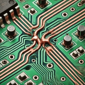
In its simplest form, a short circuit occurs when an unintended, low-resistance electrical path is created between two points in a circuit that are designed to have different electrical potentials. Instead of current flowing through the intended path(e.g., through a component with resistance), it takes the path of least resistance directly across the two points. This sudden drop in resistance leads to a surge in current flow, often far exceeding the circuit’s design limits. When this happens, several negative consequences can arise:
- Overheating:The excessive current generates significant heat, which can damage components, melt solder, or even char the PCB material itself.
- Component Damage:Sensitive components can be instantly destroyed by the high current.
- Power Supply Failure:The power supply may enter a protection mode, shut down, or fail entirely under the strain.
- Circuit Malfunction:Even if not immediately destructive, a short circuit can prevent the board from functioning correctly.
- Fire Hazard:In severe cases, extreme overheating can ignite flammable materials.
3. Common Causes of Short Circuits on PCBs
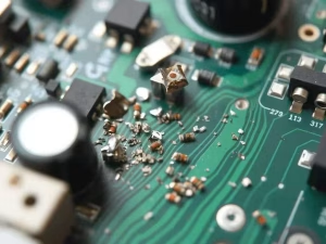
Short circuits on Printed Circuit Boards can originate from various sources, ranging from manufacturing defects to accidental damage. Understanding these causes is the first step toward effective detection and prevention:
3.1 Manufacturing and Assembly Issues
- Solder Bridges:This is perhaps the most common cause. During soldering, excess solder can inadvertently connect two adjacent pads, traces, or component leads that should remain separate. This is particularly prevalent with fine-pitch components.
- Etching Defects:In the PCB manufacturing process, errors during etching can leave unintended copper bridges between traces or pads, creating a short.
- Foreign Objects/Debris:Tiny pieces of solder splatter, wire strands, dust, or metal shavings can fall onto the board and bridge connections.
- Component Placement Errors:Components might be incorrectly placed, leading to their pins shorting against nearby traces or pads.
- Damaged Traces:During handling, assembly, or even during manufacturing, a trace might be scratched or nicked, causing it to short with an adjacent trace or ground plane.
3.2 Component-Related Shorts
- Faulty Components:Internal failures within components(e.g., a capacitor failing short, a transistor breaking down) can create a short path.
- Incorrect Component Orientation:Diodes or electrolytic capacitors installed backward can sometimes behave like a short or cause damage that leads to a short.
- Pin-to-Pin Shorts:Especially with multi-pin integrated circuits(ICs), internal defects can create shorts between pins.
3.3 Design Flaws and Environmental Factors
- Design Rule Violations:Insufficient spacing between traces, pads, or vias in the PCB layout can make the board susceptible to shorts, especially under high voltage or contamination.
- Physical Stress:Bending, dropping, or impacts can cause internal layers to short or traces to crack and bridge.
- Contamination:Moisture, conductive dust, or corrosive residues can create conductive paths on the PCB surface, leading to shorts, especially in humid or dirty environments.
4. Essential Tools and Techniques for Detecting Short Circuits
Finding a short circuit on a complex PCB can feel like searching for a needle in a haystack, but with the right tools and systematic approach, it becomes a manageable task.
4.1 Initial Visual Inspection
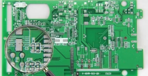
Always start here. Use a magnifying glass or a microscope. Look for:
- Solder Bridges:Tiny strands of solder connecting adjacent pads or pins.
- Burnt Marks:Darkened areas on the PCB, often indicating where excessive current flowed.
- Melted Traces:Copper traces that appear thinner, discolored, or broken.
- Damaged Components:Bulging capacitors, cracked ICs, or discolored resistors.
- Foreign Objects:Solder balls, wire strands, or other debris.
4.2 Multimeter(Digital Multimeter-DMM)
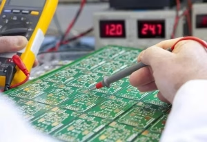
A multimeter is your primary tool for short detection.
- Continuity Mode:Set your DMM to continuity mode(usually indicated by a speaker icon). Touch the probes to the two points you suspect are shorted. A beep indicates a continuous, low-resistance path(a short). This is excellent for checking between power and ground rails, or between adjacent traces.
- Resistance Measurement:For more precise detection, use the resistance(Ohms) mode. A reading close to 0 ohms(typically under 10 ohms, depending on the circuit) between two points that should be isolated confirms a short. Higher resistance values might indicate leakage rather than a direct short.
- Systematic Checking:
1) Power-to-Ground: First, check for a short between the main power rails(e.g., VCC and GND). If a short exists here, it’s a critical issue.
2) Pin-to-Pin: Check between adjacent pins of ICs or connectors.
3) Trace-to-Trace: Check between any two traces that run close together.
4) Component Pins: Check for shorts across component pins, especially for non-resistive components like capacitors(which should show high resistance after charging).
4.3 Voltage Injection(Current Injection Method)
This method is highly effective for pinpointing shorts, especially when a multimeter only tells you a short exists but not exactly where.
1) Isolate Power: Disconnect the main power supply from the PCB.
2) Apply Low Voltage: Use a current-limited lab power supply(bench power supply). Set the voltage to a very low level(e.g., 0.5V to 2V) and the current limit to a safe, low value(e.g., 100mA to 1A, depending on the board’s complexity).
3) Inject Current: Connect the positive output of the power supply to the shorted power rail(e.g., VCC) and the negative to ground.
4) Locate Heat Signature: The current will flow through the short, causing it to heat up. You can locate this heat using:
- Thermal Camera:The most efficient method. A thermal camera will clearly show the hot spot, pinpointing the short.
- IPA(Isopropanol Alcohol) Spray:Spray IPA across the suspected shorted area. As the IPA evaporates, it will evaporate fastest over the hottest spot(the short), making it visible.
- Touch(Carefully):Lightly touch components and traces. The shorted area will feel warmer than its surroundings. Be cautious as some shorts can get very hot.
4.4 Other Advanced Techniques
- Voltage Drop Testing:With low voltage applied, measure the voltage drop along a suspected trace. The voltage will drop significantly once you pass the short.
- Current Tracer/Milli-Ohm Meter:Specialized tools designed to inject a signal and detect the path of current, very useful for finding shorts on dense boards.
- TDR(Time-Domain Reflectometry):For very complex boards or internal shorts, TDR can be used to locate discontinuities(shorts or opens) in traces by sending a pulse and analyzing its reflection.
| Detection Method | Pros | Cons | Best For |
| Visual Inspection | Fast, no equipment needed(magnifier helps) | Only external shorts, requires good eyesight | Solder bridges, obvious damage, debris |
| Multimeter(Continuity/Resistance) | Affordable, standard tool, precise resistance reading | Doesn’t pinpoint exact location on a trace/plane | Verifying presence of short, checking component health |
| Voltage/Current Injection + Thermal Camera | Highly accurate, visually pinpoints exact short location | Thermal camera can be expensive, requires bench power supply | Hard-to-find shorts, internal shorts(if external layers removed) |
| Voltage Injection + IPA Spray | Low-cost alternative to thermal camera, effective | Slower, less precise than thermal camera | Pinpointing external shorts without expensive tools |
5. Step-by-Step Guide to Fixing PCB Short Circuits
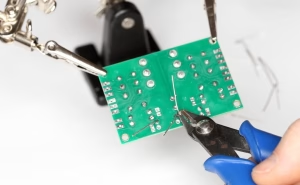
Once you’ve identified the location and nature of the short, the repair process begins. The method largely depends on the type of short detected.
Step 1: Disconnect Power
Always ensure the PCB is completely powered off and disconnected from any power source before attempting any repairs.
Step 2: Address Solder Bridges
Solder bridges are the easiest shorts to fix.
1) Heat the Bridge: Apply a clean, fluxed soldering iron tip to the solder bridge.
2) Remove Excess Solder: Use desoldering braid(wick) or a solder suck to absorb the excess solder.
3) Inspect and Clean: Visually inspect the area under magnification to ensure the bridge is completely gone. Clean the area with IPA to remove any flux residue.
Step 3: Replace Faulty Components
If your detection methods pointed to an internally shorted component:
Desolder: Carefully desolder the faulty component. Use hot air rework stations for surface mount devices(SMD) or desoldering pump/wick for through-hole components.
Clean Pads: Clean the pads thoroughly to remove old solder and flux.
Install New Component: Solder a new, known-good component in place, ensuring correct orientation.
Test: Re-test the area with a multimeter to confirm the short is gone.
Step 4: Repair Damaged Traces or External Shorts
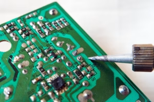
If a trace is shorted to another, or there’s a conductive foreign object:
1) Isolate the Short: If a foreign object is causing the short, carefully remove it with tweezers. If two traces are unintentionally touching, gently scrape or cut the bridge with a sharp hobby knife or a fiberglass scratch pen.
2) Repair Trace(If Needed): If the trace itself is broken or lifted due to the short, you might need to run a small jumper wire(magnet wire) to re-establish the connection.
3) Apply Solder Mask: For scraped areas, applying a UV-curable solder mask can protect the exposed copper from future shorts.
Step 5: Addressing Internal Shorts(Most Challenging)
Internal shorts, typically within multi-layer PCBs, are the hardest to fix and often lead to board replacement.
- Layer-by-Layer Removal(Destructive):In some critical cases, highly skilled technicians might carefully mill or sand down layers of the PCB to expose and isolate the short. This is extremely delicate and often unsuccessful.
- Micro-Drilling:For shorts around vias, micro-drilling might sometimes be used to remove the conductive material causing the short.
- Board Replacement:For most practical purposes, if an internal short cannot be precisely located and safely removed, replacing the entire PCB is the most common and cost-effective solution.
Step 6: Thorough Cleaning and Final Testing
After any repair, clean the area with IPA to remove flux residue. Then, perform a comprehensive test of the entire PCB to ensure all functions are restored and no new issues have been introduced.
6. Preventing Short Circuits: Best Practices
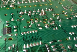
Prevention is always better than cure. Implementing robust practices throughout the design, manufacturing, and assembly stages can drastically reduce the occurrence of short circuits.
- Adhere to Design Rules:Always follow design rules for minimum trace width, trace spacing, pad-to-trace clearance, and via-to-trace clearance. Give ample room between traces, especially for high-voltage or high-current paths.
- High-Quality PCB Manufacturing:Choose reputable PCB manufacturers known for their quality control to minimize etching defects and ensure proper layer alignment.
- Proper Soldering Techniques:
1) Use the correct amount of solder and flux.
2) Ensure proper iron tip temperature and technique to prevent solder bridges.
3) Train assembly personnel on best practices for hand soldering and inspection.
- Thorough Post-Assembly Cleaning:Clean PCBs thoroughly after soldering to remove all flux residue, solder balls, and other conductive contaminants.
- Component Quality Control:Source components from reliable suppliers to reduce the risk of receiving internally faulty parts.
- Environmental Control:Maintain a clean, dust-free, and humidity-controlled work environment to prevent contamination.
- Rigorous Testing and Inspection:Implement various testing phases:
1) Automated Optical Inspection(AOI): For quickly detecting solder bridges, missing components, and correct polarity after assembly.
2) In-Circuit Test(ICT): To check individual component values and verify connectivity.
3) Functional Testing: To ensure the entire board operates as designed .
- Conformal Coating:For boards operating in harsh or humid environments, applying a conformal coating can protect against moisture-induced shorts and corrosion.
7. PCB Short Circuits FAQs
Question1: Can a short circuit permanently damage my PCB?
Yes, severe short circuits can cause permanent damage, including burnt traces, destroyed components, delamination of layers, or even complete board failure, making repair impossible or impractical.
Question2: Is a short circuit the same as an open circuit?
No, they are opposite problems. A short circuit creates an unintended low-resistance path, leading to excessive current. An open circuit is a break in the intended path, leading to no current flow(infinite resistance).
Question3: How can I prevent internal shorts on multi-layer PCBs?
Prevention relies heavily on meticulous PCB design following strict design rules, working with high-quality manufacturers, and performing thorough testing like flying probe or in-circuit testing before assembly to catch manufacturing defects early.
Question4: Can I use a multimeter to find an internal short?
A multimeter can confirm the presence of an internal short(e.g., between power and ground), but it typically cannot pinpoint its exact location within the internal layers. For that, more advanced techniques like current injection with thermal imaging or specialized TDR equipment are often needed.
Question5: What is the safest voltage to use for current injection to find a short?
Start with a very low voltage, typically between 0.5V and 2V, and a current limit of 100mA to 1A. The goal is to generate just enough heat at the short without damaging other components. Always monitor the temperature carefully.
8. Summary
Short circuits on Printed Circuit Boards pose a significant threat to electronic devices, potentially causing malfunctions, damage, or even safety hazards. Understanding their causes, which range from manufacturing defects like solder bridges and etching errors to faulty components and environmental factors, is crucial for both prevention and repair. Effective detection relies on a systematic approach, starting with visual inspection and progressing to essential tools like multimeters for continuity and resistance checks. For precise localization, current injection combined with thermal imaging or IPA spray is invaluable. While external shorts like solder bridges and component failures are often repairable with careful desoldering and replacement, internal shorts in multi-layer PCBs frequently necessitate board replacement. Ultimately, adhering to stringent design rules, employing high-quality manufacturing, practicing meticulous assembly, and implementing rigorous testing throughout the product lifecycle are the best defenses against these disruptive faults.
Key Takeaways
- PCB short circuits are unintended low-resistance paths causing excessive current, heat, and potential damage.
- Common causes include solder bridges, etching defects, faulty components, design flaws, and physical damage.
- Start detection with a visual inspection, followed by a multimeter for continuity and resistance checks.
- Current injection with a thermal camera or IPA spray is highly effective for pinpointing hard-to-find shorts.
- Fix external shorts(solder bridges, component failures) by careful desoldering and replacement.
- Internal shorts are often difficult to repair and may require board replacement.
- Prevention is key: adhere to design rules, ensure quality manufacturing, use proper soldering techniques, and implement thorough testing.
OrinewPCB has focused as a one-stop PCB assembly manufacturer from PCB Manufacturing to Electronic Components Sourcing to PCB Assembly to Test to Program IC for more than 14 Years with reliable quality and fastest delivery for global clients.








