FR4 vs. Rogers: Choosing the Right PCB Material for Your Design

Table of Content
1. The Critical Choice of PCB Materials
In the rapidly evolving world of electronics, the performance of a Printed Circuit Board(PCB) is paramount, often dictated by the materials from which it’s constructed. For decades, FR4 has been the unchallenged default for most PCB designs, lauded for its cost-effectiveness and versatile performance in a wide array of applications. However, with the relentless march of technological innovation—driven by demands for faster internet, high-definition mobile video, and the proliferation of IoT devices—the landscape of PCB design is shifting dramatically. Modern systems now require PCBs to meet stringent high-frequency performance standards while simultaneously supporting ultra-high-speed digital data transfer. This evolution, particularly in areas like 5G infrastructure, big data centers, and advanced RF applications, has brought a critical decision to the forefront: FR4 or specialty laminates like Rogers?
The moment a project introduces signals over 5 GHz, designers and procurement managers are confronted with the “Rogers vs. FR4” dilemma. This isn’t merely a technical specification; it’s a significant negotiation between performance requirements, manufacturing complexity, and, crucially, cost. While specialty laminates such as Rogers can significantly elevate PCB capabilities, they often come with a higher price tag, sometimes doubling the PCB cost depending on factors like thickness, copper type, and availability. This guide provides a calculated framework to help you understand the core differences between these two prominent PCB materials and determine when the cost of specialized high-frequency materials is truly justified for your unique printed circuit board design.
2. Understanding FR4: The Industry Workhorse
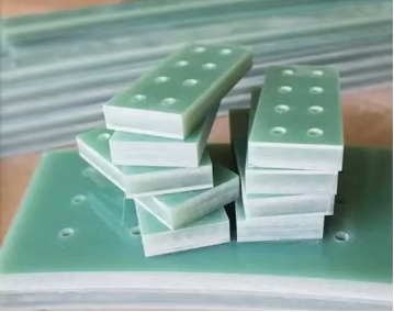
FR4 is an acronym for “Fire Retardant, Grade 4”, indicating its flammability rating(it’s self-extinguishing rather than fire-proof). It represents the industry standard for general-purpose PCBs due to its balanced properties and economic viability. FR4 material is primarily composed of woven fiberglass fabric impregnated with an epoxy resin binder, then laminated with copper foil. This composite structure gives FR4 its characteristic strength, electrical insulation, and manufacturability.
Key Characteristics of FR4 Materials:
- Dielectric Constant(Dk):Typically ranges from 4.2 to 4.7. While suitable for many applications, this Dk can vary significantly with frequency, leading to impedance control challenges in high-frequency designs.
- Dissipation Factor(Df):Usually between 0.015 and 0.020. This relatively higher Df means that FR4 exhibits greater signal loss, especially as frequencies increase, making it less ideal for RF applications or high-speed digital signals where signal integrity is critical.
- Thermal Properties:FR4 has a glass transition temperature(Tg) ranging from 130°C to 180°C. Above this temperature, the material softens and loses some of its rigidity. Its coefficient of thermal expansion(CTE) is also higher than copper, which can cause stress on plated through-holes during thermal cycling.
- Cost-Effectiveness: This is FR4’s primary advantage. It is significantly more affordable than specialty laminates, making it the material of choice for budget-conscious projects and consumer electronics.
- Ease of Manufacturing:FR4 is widely available and easy to process, drill, and fabricate using standard PCB manufacturing techniques.
- Applications:Ideal for low to mid-frequency digital circuits, power supplies, consumer electronics, and most general-purpose applications where signals are below 1 GHz and signal loss is not a critical concern.
Despite its limitations at higher frequencies, FR4 remains an excellent choice for a vast majority of PCBs due to its proven reliability, widespread availability, and attractive price point. However, as operating frequencies climb, its electrical properties become less stable and predictable, prompting the need for more specialized alternatives.
3. Exploring Rogers Materials: High-Performance Solutions
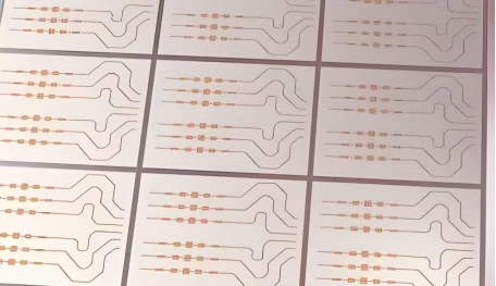
Rogers Corporation manufactures a range of high-performance laminates, often referred to simply as “Rogers materials”, designed specifically to overcome the limitations of FR4 in demanding applications. These materials are typically made from ceramic-filled PTFE(Polytetrafluoroethylene), thermoset resins, or hydrocarbon ceramics. Unlike FR4, which uses a woven glass epoxy, Rogers laminates are engineered to provide superior electrical and thermal performance, particularly at high frequencies.
Key Characteristics of Rogers Materials:
- Dielectric Constant(Dk):Rogers materials offer a wide range of Dk values, typically from 2.2 to 11. These values are highly stable across varying frequencies and temperatures, which is crucial for maintaining impedance control and predictable performance in high-frequency PCB designs. Examples include Rogers RT/duroid 5880 (Dk ~2.2) and Rogers RO4350B (Dk ~ 3.66).
- Dissipation Factor(Df):Rogers laminates boast very low Df values, often below 0.004. This translates to significantly lower signal loss at high frequencies compared to FR4, making them indispensable for applications where every decibel of signal strength matters. This property is vital for ensuring signal integrity in high-speed digital and RF circuits.
- Thermal Stability:These materials exhibit excellent thermal stability, with a lower coefficient of thermal expansion(CTE) that closely matches that of copper. This minimizes stress on plated through-holes and improves reliability over temperature cycles. They also generally have higher Tg values or are thermoset materials with no Tg, providing stable performance across a wide temperature range.
- Moisture Absorption:Rogers materials typically have very low moisture absorption rates, which helps maintain stable Dk and Df values, preventing performance degradation in humid environments.
- Cost:The superior performance comes at a premium. Rogers materials are considerably more expensive than FR4, and their specialized nature can sometimes lead to longer lead times and higher fabrication costs.
- Applications:Essential for high-frequency PCB applications, including RF, microwave circuits, 5G base stations, satellite communication systems, radar systems, high-speed digital backplanes, and critical impedance-controlled designs where low signal loss and stable Dk are paramount .
The specialized composition and precise manufacturing processes of Rogers materials make them the go-to choice when the electrical demands of an application exceed FR4’s capabilities, especially in sensitive high-frequency environments where maintaining signal integrity is non-negotiable.
4. FR4 vs. Rogers: A Detailed Comparison
Choosing between FR4 and Rogers materials for your PCB project hinges on a thorough understanding of their fundamental differences and how these impact performance, manufacturing, and cost. Below is a detailed comparison across key parameters:
| Feature | FR4 (Standard Epoxy/Woven Glass) | Rogers (Specialty Laminates e.g., RT/duroid, RO4000 series) |
| Composition | Woven fiberglass fabric impregnated with epoxy resin. | Ceramic-filled PTFE, hydrocarbon ceramics, or thermoset resins(no woven glass). |
| Dielectric Constant(Dk) | 4.2 – 4.7 (Varies with frequency, temperature) | 2.2 – 11(Stable across frequency and temperature) |
| Dissipation Factor(Df)/Loss Tangent | 0.015 – 0.020(Higher signal loss) | 0.001 – 0.004(Very low signal loss) |
| Thermal Stability(Tg) | 130°C – 180°C(Softens above Tg) | Higher Tg or no Tg(thermoset), excellent thermal stability. |
| Coefficient of Thermal Expansion(CTE) | Higher, especially in Z-axis(can cause PTH stress) | Lower, closely matched to copper(improves PTH reliability ) |
| Moisture Absorption | Higher(can affect Dk/Df stability) | Very low(stable electrical properties) |
| Impedance Control | Good at lower frequencies, challenging at high frequencies due to Dk variation. | Excellent due to stable and precise Dk values. |
| Cost | Low(industry standard, cost-effective) | High(specialty material, significantly more expensive) |
| Manufacturing | Easy to process, standard fabrication techniques. | Requires specialized equipment and processes; can be more challenging. |
| Typical Applications | Low-frequency digital, consumer electronics, power supplies, general purpose. | RF/Microwave circuits, 5G, radar, high-speed digital, satellite communication. |
This comparison clearly illustrates that while FR4 offers a cost-effective solution for a broad spectrum of applications, its electrical and thermal limitations become apparent as frequency and performance demands increase. Rogers materials, on the other hand, are engineered to excel in these challenging high-frequency environments, providing the stable electrical properties and thermal reliability necessary for advanced electronics.
5. When to Choose FR4 vs. Rogers for Your Design?
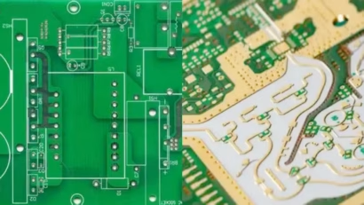
The decision between FR4 and Rogers materials is a critical engineering trade-off that balances performance requirements with budget constraints. Making the right choice involves evaluating several key factors:
5.1 Choose FR4 Materials When:
- Budget is a Primary Concern:If cost-effectiveness is paramount and performance requirements are moderate, FR4 is almost always the more economical choice. It can be significantly cheaper, especially for prototyping and high-volume production of less demanding boards.
- Operating Frequencies are Low to Moderate:For signals below 1-2 GHz, FR 4 typically performs adequately. Applications like general digital circuits, power management, LEDs, and basic consumer electronics don’t usually require the advanced electrical properties of Rogers.
- Signal Loss is Tolerable:If a certain amount of signal attenuation can be accommodated without compromising system functionality, the higher dissipation factor of FR4 is not a deal-breaker.
- Thermal Management is Standard:For designs with moderate power dissipation and operating temperatures, FR4’s thermal properties are sufficient.
- Rapid Prototyping and Widespread Availability are Needed:FR4 is readily available from nearly all PCB manufacturers, allowing for quicker turnaround times and simpler fabrication processes.
5.2 Choose Rogers Materials When:
- High-Frequency Performance is Critical:If your design involves RF, microwave, millimeter-wave(mmWave), or high-speed digital signals(e.g., above 5 GHz , for applications like 5G infrastructure or high-speed data transfer), Rogers laminates are indispensable. Their stable Dk and very low Df minimize signal loss and maintain impedance control.
- Signal Integrity is Paramount:For designs where precise impedance matching, minimal signal distortion, and cross-talk are crucial, Rogers materials provide superior electrical stability, leading to better signal integrity.
- Thermal Stability and Reliability are Key:In environments with wide temperature fluctuations or where heat generation is significant, Rogers materials with their low CTE and excellent thermal properties ensure long-term reliability and prevent issues like delamination or plated through-hole failures.
- Strict Impedance Control is Required:When precise line impedance are necessary for optimal performance, the consistent dielectric constant of Rogers materials makes design and manufacturing much more predictable.
- Low Moisture Absorption is Desired:For applications in humid or harsh environments where moisture can degrade electrical performance, Rogers materials offer superior resistance.
- High-Power RF Applications:The thermal conductivity of certain Rogers materials also makes them suitable for high-power RF applications where efficient heat dissipation is needed.
Ultimately, the choice comes down to a careful assessment of the application’s specific technical demands, the required performance margins, and the available budget. Sacrificing performance for cost can lead to unreliable or non-functional products, while over-specifying can unnecessarily inflate project expenses.
6. Impact on High-Frequency and High-Speed Designs
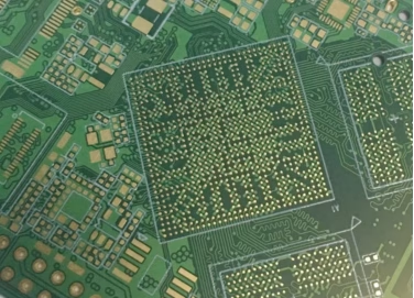
The increasing complexity and speed of modern electronics have made the choice of PCB material a primary factor in the success of high-frequency and high-speed designs. In these demanding applications, the material’s properties directly impact signal propagation, integrity, and overall system performance.
1) Signal Loss and Dissipation Factor(Df)
One of the most significant impacts relates to signal loss. As frequencies increase, so does the attenuation of signals propagating through the PCB substrate. The dissipation factor(Df) of the material is a key indicator of this loss. FR4, with its higher Df, experiences substantially more signal loss at higher frequencies compared to Rogers materials. For RF applications like antennas, filters, and amplifiers, or for high-speed digital buses operating at multi-gigabit speeds, this loss can be detrimental, leading to reduced range, decreased data rates, and increased power consumption. Rogers materials, engineered with very low Df, minimize this loss, ensuring that signals arrive at their destination with maximum strength and fidelity.
2) Dielectric Constant(Dk) Stability and Impedance Control
Impedance control is paramount in high-frequency circuits to prevent reflections and maintain signal integrity. The dielectric constant(Dk) of the PCB material directly influences trace impedance. FR4’s Dk can vary significantly with frequency, temperature, and even moisture content. This variability makes it challenging to maintain precise impedance control across a broad range of operating conditions, potentially leading to signal reflections, increased noise, and degraded performance. Rogers materials, conversely, offer highly stable Dk values that are consistent across frequency and temperature. This stability allows for accurate impedance calculation and manufacturing, ensuring predictable performance for critical signal paths in high-frequency PCB designs.
3) Thermal Management and Reliability
High-frequency and high-speed circuits often generate considerable heat. The thermal properties of the PCB material play a crucial role in managing this heat and ensuring long-term reliability. FR4’s higher coefficient of thermal expansion(CTE), especially in the Z-axis, can cause stress on plated through-holes(PTHs) during thermal cycling, leading to fractures and intermittent connections over time. Rogers materials typically have lower CTEs that closely match that of copper, significantly improving PTH reliability and overall board lifespan in thermally challenging environments. Their superior thermal stability ensures consistent electrical performance even under varying operating temperatures.
4) Crosstalk and EMI
In densely packed high-speed boards, crosstalk and electromagnetic interference(EMI) are major concerns. While board layout and stack-up are primary factors, the material’s dielectric properties also play a role. The more controlled and stable the dielectric environment, the better the overall signal integrity and reduced potential for unintended coupling between traces. Rogers materials provide a more uniform and predictable electrical environment, which can indirectly contribute to better management of crosstalk and EMI.
In essence, while FR4 might suffice for simpler, lower-frequency designs, the escalating demands of modern electronics—especially in domains like 5G, radar, satellite communications, and high-performance computing—make the advanced electrical and thermal properties of Rogers materials indispensable for achieving optimal performance, reliability, and ensuring signal integrity.
7. Balancing Cost and Performance in PCB Design
The decision between FR4 and Rogers materials often boils down to a fundamental engineering challenge: how to balance required performance with acceptable cost. While the technical advantages of Rogers materials for high-frequency applications are undeniable, their higher price point necessitates careful consideration.
1) The Price Tag
Rogers materials are typically several times more expensive than FR4. This cost difference stems from several factors: specialized raw materials(like PTFE), more complex manufacturing processes, and lower production volumes compared to the ubiquitous FR4. For prototyping, the material cost alone can easily double the overall PCB fabrication expense, and for mass production, these costs scale significantly. This financial reality means that for many consumer electronics or general-purpose devices, the superior performance of Rogers simply cannot be justified economically.
2) The Hidden Costs of Choosing Poorly
However, opting for the cheapest solution without considering performance needs can lead to its own set of “hidden” costs:
- Performance Degradation:Using FR4 in high-frequency applications(e.g., 5G modules) can result in excessive signal loss, impedance mismatches, and reduced signal integrity, leading to sub-optimal product performance, reduced range, or lower data rates.
- Rework and Redesign:If a design fails to meet specifications due to material limitations, expensive and time-consuming redesigns, re-fabrication, and re-testing become necessary.
- Market Competitiveness:In highly competitive markets, a product that underperforms due to material choices can lose out to competitors utilizing optimized materials.
- Reliability Issues:Inadequate thermal management or mechanical stability from an unsuitable material can lead to premature product failure, warranty claims, and damage to brand reputation.
3) Strategic Material Selection
A calculated, professional framework is essential for making the right choice. Consider these strategies:
- Define Requirements Clearly:Begin by precisely defining the operating frequency, signal speed, power handling, thermal environment, and required signal integrity for your printed circuit board design.
- Segment the Design:For complex boards with mixed signals(e.g., low-speed digital and high-frequency RF sections), consider hybrid solutions. This could involve using FR4 for the majority of the board and selectively incorporating Rogers laminates for critical RF sections, potentially in a multi-layer stack-up, to optimize both performance and cost.
- Prototype and Test:Whenever feasible, prototype with both materials(or similar alternatives) to empirically validate performance and identify potential issues before committing to a final material choice.
- Consult with Manufacturers:Engage with your PCB fabrication partner early in the design process. They can offer insights into material availability, fabrication complexities, and potential cost savings based on their experience.
- Long-Term Value:Evaluate the total cost of ownership, including potential performance gains, extended product lifespan, reduced field failures, and improved customer satisfaction, against the initial material cost. Sometimes, the higher initial investment in Rogers materials can lead to significant long-term savings and a superior product.
In conclusion, while FR4 is a cost-effective PCB material, for the increasingly demanding world of high-frequency and high-speed electronics, the investment in Rogers materials often translates into a more reliable, higher-performing, and ultimately more successful product. The key is to avoid over-engineering where FR4 suffices, but never under-engineering where Rogers is truly required.
8. FR4 and Rogers PCB Material FAQs
The main difference lies in their dielectric constant(Dk) and dissipation factor(Df). Rogers materials have a more stable and lower Dk, and a significantly lower Df, resulting in less signal loss and better impedance control at high frequencies compared to FR4.
While FR4 can be used for some lower-end high-frequency applications(typically below 1-2 GHz), its Dk variability and higher Df lead to increased signal loss and unpredictable impedance at higher frequencies, making it unsuitable for critical RF or high-speed digital designs above 5 GHz.
Rogers materials use specialized raw ingredients(like ceramic-filled PTFE) and require more complex manufacturing processes. These factors, combined with lower production volumes compared to FR4, contribute to their higher cost.
Yes, Rogers materials generally offer superior thermal stability, with a lower Coefficient of Thermal Expansion(CTE) that closely matches copper, reducing stress on plated through-holes and improving reliability in varying temperature conditions. Some Rogers laminates also have higher thermal conductivity.
Yes, hybrid stack-ups are common. Designers can use FR4 for the majority of the board and integrate Rogers laminates for specific high-frequency or RF sections to optimize both performance and cost. This is often achieved by combining different prepregs and core materials.
9. Summary
The choice between FR4 and Rogers materials is a pivotal decision in printed circuit board design, directly influencing performance, cost, and reliability. FR4, the industry standard, offers a cost-effective and versatile solution for low to mid-frequency applications due to its balanced properties and ease of manufacturing. However, its higher dielectric constant variability and dissipation factor lead to significant signal loss and impedance control challenges at frequencies above 1-2 GHz.
Rogers materials, on the other hand, are specialty laminates engineered for demanding high-frequency and high-speed applications. They boast stable and precise dielectric constants, extremely low dissipation factors(minimizing signal loss), and superior thermal stability. These characteristics make them indispensable for RF, microwave, 5G infrastructure, and high-speed digital designs where signal integrity and predictable performance are paramount, despite their considerably higher cost. Ultimately, a careful evaluation of the specific technical requirements, operating environment, and budget constraints is crucial for selecting the right PCB material to ensure a successful and reliable electronic product.
Related Posts
ORINEWPCB · PROJECT SUPPORT
Contact Us
Discuss your PCB assembly project with our team.
FREE QUOTE
Plan your turnkey PCBA build.
Share your quantity and requirements. Add Gerber files and a BOM when ready.
Files are optional for an initial discussion. Include any assembly, sourcing or testing requirements in your message.