Conformal Coating Masking: PCB Keep-Out Drawing & Checklist
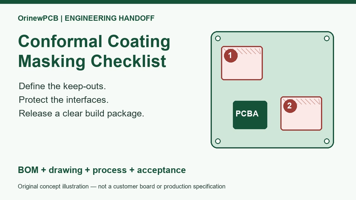
Table of Content
Conformal coating masking keeps specified contacts, openings and functional interfaces free of coating while the required areas receive protection. For a turnkey PCB assembly order, release a coating drawing with top and bottom views, identified keep-outs, boundary tolerances, the approved coating system and an agreed inspection plan. “Mask all connectors” is not a complete production instruction.
This guide answers a practical engineering and purchasing question: what must you put in a coating masking drawing so your PCBA supplier can quote and build the intended result? It focuses on the release package and acceptance decisions, rather than choosing a universal coating chemistry or inventing one masking clearance for every board.
For a complete build, send your PCB files, BOM and coating requirements for a turnkey PCBA review. Include your quantities for each model and variant.
1. What masking must preserve
A conformal coating can protect designated circuit areas, but the same material can interfere with a connection, opening or service operation if it reaches the wrong surface. Specify the interface that must remain usable, not merely the name of the nearby component.
For example, a connector’s mating contacts and a connector’s soldered terminals have different functions. Whether the body, terminals or surrounding board can be coated depends on the exact part, coating and approved process. A sealed-looking housing is not evidence that liquid or vapor cannot enter it.
Masking also has a removal stage. A temporary protection that works during application must come off at the required point without leaving obstructive residue or damaging the assembly. Application, curing and removal conditions therefore belong in the process review.
Keep three decisions separate: which surfaces require coating, which surfaces must stay uncoated, and how each boundary will be produced and inspected. Areas with unresolved requirements should be marked for engineering review before production release.
2. Which areas need a coating keep-out review?
The table is a review checklist, not a blanket prohibition on coating every component in a category. Follow the exact component manufacturer’s instructions and your product requirements.
| Interface | What to identify | Decision to release |
|---|---|---|
| Connectors and contacts | Mating surfaces, card-edge fingers, sockets and access openings. | Exact no-coat surfaces, allowed treatment of the body or terminals, and the check after removal. |
| Sensing or acoustic openings | Humidity/gas sensor openings, pressure ports and acoustic paths where applicable. | Part-specific protection method, chemical compatibility and the required open condition in service. |
| Programming and test contacts | Contacts required before coating, after coating or during field service. | Test sequence and which contacts must remain accessible in the shipped state. |
| Mechanical and bonding surfaces | Specified ground bonds, mounting interfaces, threads and fitted mating faces. | Dimensions and contact requirements; do not assume every mounting hole has the same rule. |
| Adjustments and moving parts | Switch mechanisms, adjustments, removable links and serviceable parts. | Allowed process exposure and post-process access or movement checks. |
Sensor example: an exposed humidity-sensing opening must remain functional and free of the prohibited coating. A manufacturer-approved temporary cover can have its own removal instruction. Do not apply generic tape directly to every sensor: the permitted method and sensitivity to processing chemicals depend on the actual device.
3. Build a masking drawing that can be inspected
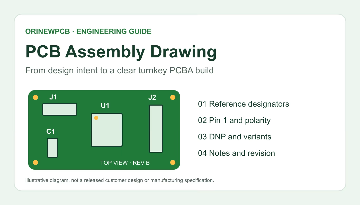
Start with the released assembly identity: board number, PCB revision, assembly revision and variant. Show the top and bottom sides with enough reference designators to identify each restriction. Use a clear legend for “coat,” “do not coat” and “engineering review required.” Color helps, but hatching and text should also make the meaning readable in a monochrome print.
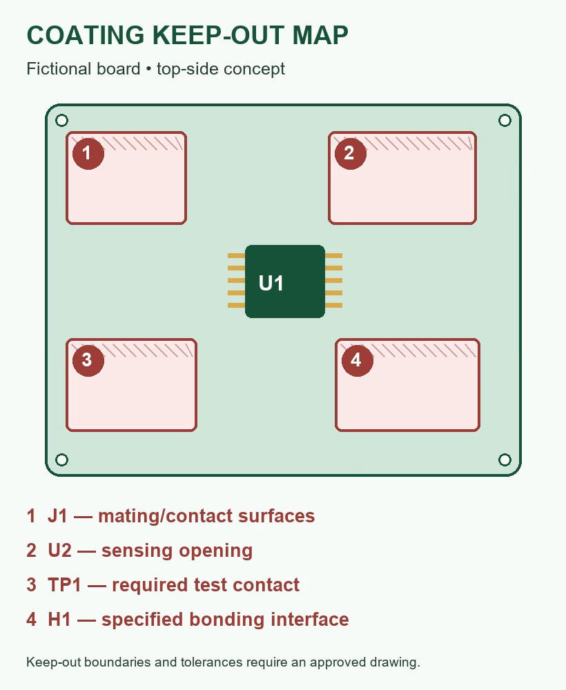
For each restricted area, define the surface or boundary in a view that the operator and inspector can actually use. A note pointing at a connector may not show whether the restriction covers only its opening, the whole body or adjacent PCB copper. Add a detail view when the main view is ambiguous.
- Identify the build. State the board, assembly revision, variant and coating drawing revision.
- Define each surface. Link the region to a reference designator, interface or dimensioned feature; identify the side.
- Specify the boundary. Provide the required limit and permitted boundary variation, with units and a datum where needed. Have the assembler confirm that the process can achieve it.
- Define the coating system. Identify the approved product or controlled specification, thickness requirement and cure/handling criteria appropriate to the selected material.
- Record process-sensitive parts. Include component restrictions and the approved protection/removal method where needed.
- Define acceptance. Specify coverage, restricted surfaces, required inspection evidence and any functional checks.
There is no single masking clearance that is suitable for every spray valve, coating viscosity, connector geometry or assembly. A tight boundary beside a tall component deserves a manufacturability discussion before the PCB layout and quote are frozen.
Keep this drawing linked to the PCB assembly drawing. If a BOM alternative changes a connector body or sensor package, revisit its masking instructions before approving that substitution.
4. Compare the masking method with the build
Temporary tapes, caps, plugs, peelable masks and fixtures can serve different geometries. Selective application controls where coating is delivered; it does not remove the need to define the finished keep-outs. The supplier should review the actual part geometry, material compatibility, exposure conditions and removal access.
| Approach | Useful review point | What to confirm |
|---|---|---|
| Tape, cap or plug | Temporary protection of a defined accessible interface. | Fit, attachment, chemical/temperature compatibility, removal and residue acceptance. |
| Peelable masking material | Temporary masking shaped to a particular area. | Compatibility, application and removal timing from its instructions, plus access for complete removal. |
| Reusable fixture or mask | A repeatable arrangement for a specified board and component geometry. | Revision control, fit, maintenance, cleaning and any variant-specific differences. |
| Selective coating program | A controlled application path around released no-coat regions. | Access, flow and boundary behavior on the real assembly; remaining physical masking needs. |
Do not transfer the removal timing of one peelable product to another. Coating and masking suppliers provide material-specific instructions. The same caution applies to cure temperatures and cleaning: a generally suitable board-cleaning step may be unsuitable for an exposed sensor.
5. Agree on testing, removal and first-build acceptance
A practical sequence starts with an approved release package and includes inspection of the assembled board before coating hides access. Programming or functional testing may occur at a different point for different products. State the intended sequence and required contact access explicitly.
- Confirm assembly identity and complete the agreed pre-coating checks.
- Prepare the assembly using compatible, approved cleaning and drying procedures.
- Apply the released masking and verify the protected interfaces.
- Apply and cure the specified coating under its approved process.
- Remove temporary protection at the stage required for that material and assembly.
- Inspect coverage, boundaries, removal and interface access; perform the agreed final checks.
A visual or UV inspection, where supported by the coating system, helps assess coverage. It does not by itself prove film thickness, electrical function or environmental qualification. Define each required measurement and test separately.
For a first build, agree which views or records must be reviewed and whether a customer approval hold is required before the remainder is processed. A sample photograph is useful evidence of an identified feature; it is not a substitute for all acceptance requirements.
6. Example: resolve one masking conflict before production
Consider a fictional controller assembly whose drawing says “mask J1,” while the BOM alternative list permits two connector bodies with different shapes. The coating program was prepared around only one body. The proper next step is a controlled clarification, not an operator guessing which file wins.
Assembly: Controller Rev C, Variant B — fictional example.
Issue: approved connector choices have different masking geometry.
Required decision: identify the MPN used for this build and release the correct keep-out detail and masking/program revision.
Verification: confirm mating access and the agreed coating boundary on the first build.
Release record: record the approver, drawing revision and applicable lot or quantity before continuing.
For high-mix production, use a variant matrix rather than assuming one mask fits every product. The matrix can identify assembly revision, fitted MPN, masking drawing, fixture/program revision, removal instruction and test procedure. A new component source alone may not change geometry; a different approved MPN can. Review the actual change.
7. Checklist for a turnkey PCBA quote with coating
Help the assembler quote the finished requirement, including masking work, tooling, curing and inspection. Useful inputs are:
- Gerber/manufacturing files, released BOM, placement data and assembly drawing.
- Model/variant quantities and whether shipment is coated PCBA or a further assembled product.
- Top/bottom coating views, keep-out details, boundary requirements and exact coating specification.
- Restrictions from the component documentation, including exposed sensors, connectors and temporary covers.
- Programming/test sequence, post-coating test access, fixtures and pass/fail criteria.
- Required inspection records, first-build approval and any qualification or traceability requirements.
- Target delivery date and whether proposed material changes need written approval.
Ask that one-time tooling or programming and recurring masking/inspection work be identified clearly in the quote. Price and schedule depend on the released design, selected materials, quantities and process scope. A standard coating material alone does not establish the suitability of the complete product for its environment.
Review the complete build with OrinewPCB
OrinewPCB provides turnkey PCB assembly, PCB manufacturing and component procurement, with particular strength in high-mix, small-to-medium batches. Our sourced components and components used for turnkey PCBA follow our 100% brand-new, original genuine material policy.
We have conformal coating equipment and can review coating and masking requirements as part of your project. Send your files, quantities and keep-out instructions so we can assess feasibility, the required process and an appropriate quote. Inspection coverage and functional testing are agreed for the build.
Request a Turnkey PCBA & Coating Review
Review our factory and quality workflow, or visit the OrinewPCB brand assembly overview.
8. Conformal coating masking FAQ
Does selective coating mean that physical masking is unnecessary?
Not automatically. Selective coating controls the application path. The actual design may still need protection against flow, access limitations or other process effects. Release the required finished boundary and have the supplier confirm the method.
Should all connectors be left completely uncoated?
Define the exact surfaces that must remain free of coating, particularly mating contacts and required openings. Treatment of the body, terminals and adjacent board depends on the specific connector, coating and approved process.
What masking clearance should I put on my drawing?
Use the boundary and tolerance your design requires, then review manufacturability with the assembler. There is no universal clearance suitable for every coating, application method and component geometry.
Can test points be coated after the board passes its first test?
Only if the released requirements allow it. Consider tests after coating, programming, rework and service access. Specify which contacts must remain accessible in the shipped product.
Does a temporary sensor cover make every coating process safe?
No. Check the exact sensor and cover instructions, coating compatibility and removal sequence. A cover that blocks liquid does not necessarily protect against every processing vapor or chemical exposure.
Can one masking drawing cover several PCBA variants?
Yes, if it unambiguously identifies all applicable variants and their differences. Use a controlled matrix or separate details when fitted components, keep-outs, tooling or test access change.
What if my coating drawing is not ready?
Send the assembly files and describe the interfaces that must remain usable, the environment and any specified material. Ask for a preliminary review. Approve the coating and masking requirements before production proceeds.
Related Posts
ORINEWPCB · PROJECT SUPPORT
Contact Us
Discuss your PCB assembly project with our team.
FREE QUOTE
Plan your turnkey PCBA build.
Share your quantity and requirements. Add Gerber files and a BOM when ready.
Files are optional for an initial discussion. Include any assembly, sourcing or testing requirements in your message.