
A Complete Guide to LED PCBs: From Design Basics to Manufacturing

Table of Content
LEDs are everywhere today—from home lighting to car headlights and electronic displays. But an LED is only as good as the circuit board it sits on.
This guide explains how LED PCBs work and how to design them. Written for both beginners and experienced engineers, it covers the complete process: what LED PCBs are, how to choose materials, step-by-step design methods, thermal management, and assembly options.
1. What is an LED PCB?
1.1 What is an LED PCB?
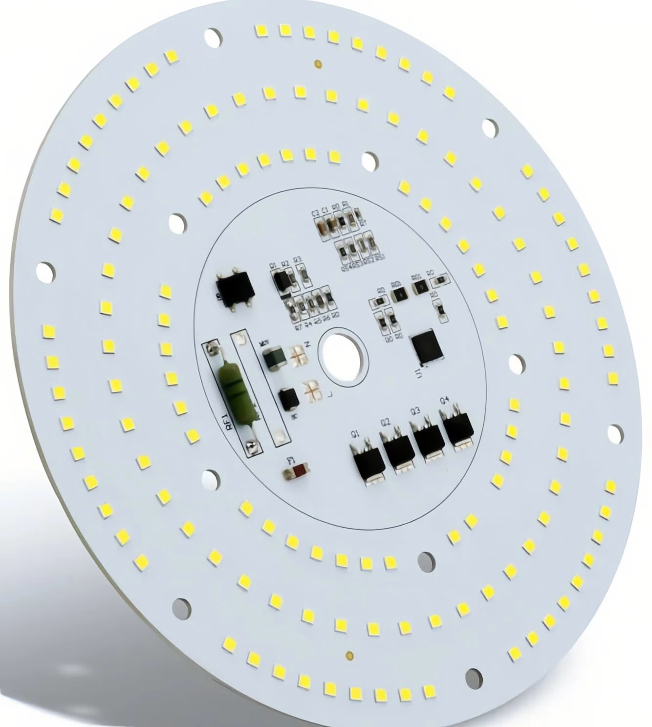
An LED PCB, or Light Emitting Diode Printed Circuit Board, is a specialized circuit board made for mounting and powering LED lights. It is more than just a physical holder for the LEDs. It is a key system that combines electrical connections, mechanical support, and heat management.
Unlike standard PCBs, an LED PCB must handle the significant heat that LEDs produce during operation. It also needs to distribute electrical current precisely. This ensures that every LED has consistent brightness and color, and that the whole system works reliably for a long time.
The basic working principle is simple. Copper traces on the PCB act as electrical paths. They carry current from the power source accurately to each LED chip. At the same time, the special base material and design of the board pull heat away from the LEDs quickly. This stops heat from building up, which can cause poor performance or early failure.
1.2 Key Components
A typical LED PCB is made up of several key parts:
- Substrate: This is the foundation of the PCB. It provides mechanical support. Depending on the use, the substrate can be standard FR-4 (a flame-retardant fiberglass and epoxy material). For better heat transfer, it can also be a metal core, often aluminum or sometimes copper.
- Circuit Layer (Copper Foil): This is a thin layer of copper bonded to the substrate. It is etched to form the intended circuit pattern, or copper traces. These traces carry the electric current to each LED.
- Thermal Insulation Layer: This is a critical layer found in Metal Core PCBs (MCPCBs). It sits between the circuit layer and the metal base. Made from a ceramic-filled polymer, it has high thermal conductivity and high electrical insulation. It efficiently conducts heat to the metal base while preventing electrical shorts between the circuit and the metal.
- Solder Pads: These are specific areas on the copper traces. They are used to solder the LEDs or other components, creating the electrical connection.
- Solder Mask: This is a protective ink layer covering the copper traces. It prevents accidental shorts during soldering, stops oxidation, and marks where components should be placed.
- Components: Besides the LED chips themselves, the PCB may have other parts. These include current-limiting resistors, capacitors, constant-current driver ICs, and connectors. They are all needed for the circuit to work correctly.
2. Classifications of LED PCB
LED PCBs can be grouped by the base material they use or by the application they are designed for.
2.1 Classification by Base Material
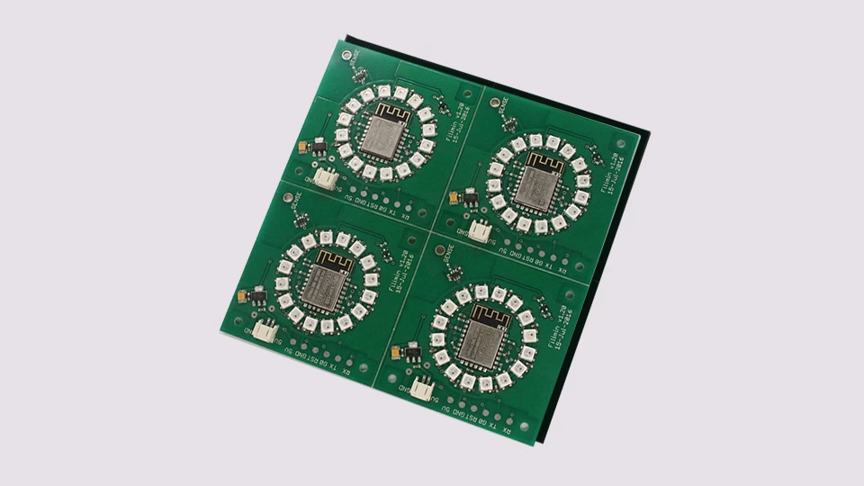
- Standard FR-4 PCB: This type uses fiberglass and epoxy resin as the base. It is the most cost-effective option. It works well for low-power LEDs that do not generate much heat. Common uses are small indicator lights or simple decorative lamps. However, its thermal conductivity is poor. It is not suitable for high-power applications.
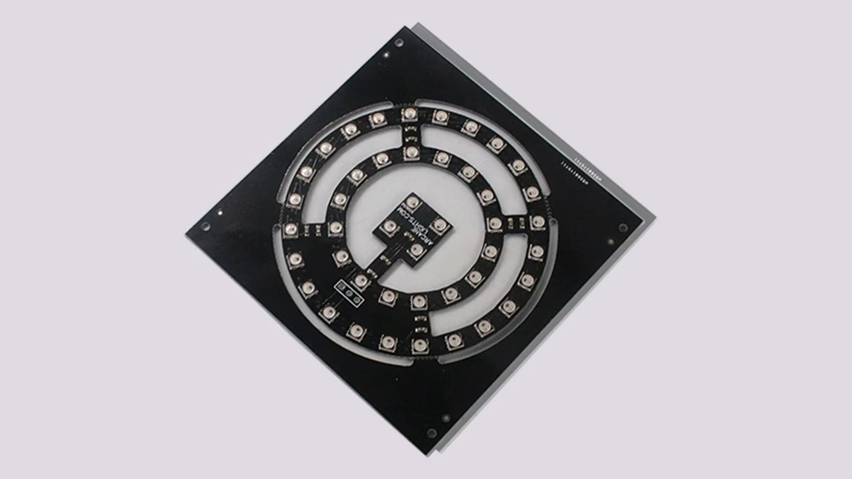
- Metal Core PCB(MCPCB): This design was developed to handle the heat from high-power LEDs. The most common metal base is aluminum. Aluminum is popular because it has good thermal conductivity, costs less, is lightweight, and is durable. For very demanding uses, like high-power spotlights or car headlights, a copper core might be used. Copper conducts heat much better than aluminum, but it costs more and is heavier.
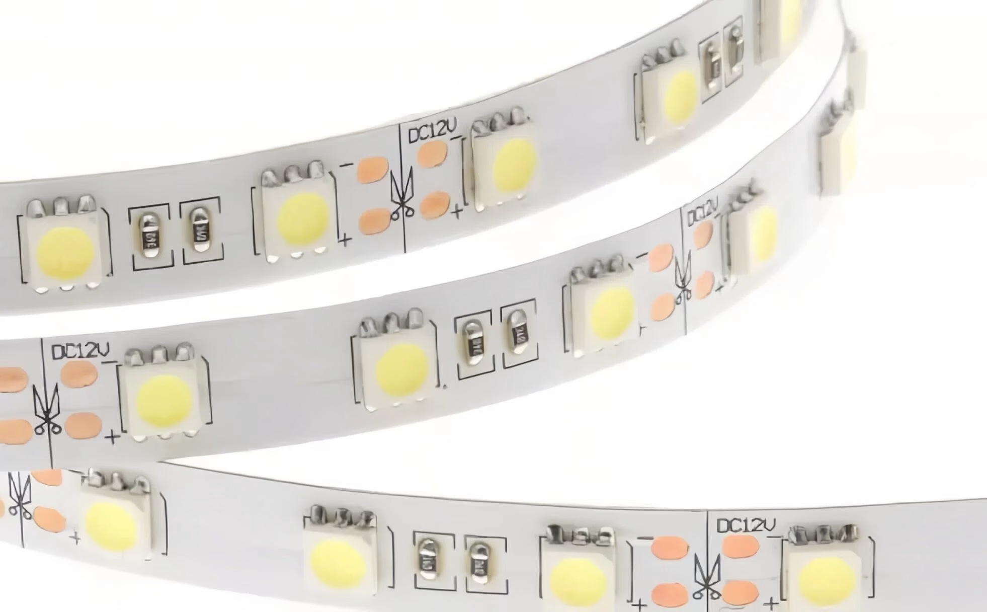
- Flexible PCB: The base material here is a flexible plastic, like polyimide. This allows the whole circuit board to bend. Flexible PCBs are often used for LED strip lights, wearable devices, or any lighting design that needs to fit into an irregular or curved space.
2.2 Classification by Application
- LED Strip PCB: These are usually long, narrow boards, either flexible or rigid. They have LEDs placed at regular intervals. They are used for decorative lighting or outlining shapes.
- LED Panel PCB: These are designed as larger panels. They have many LEDs arranged in a matrix on the surface. They are used for general lighting in places like offices and shopping malls.
- High-Power LED PCB: These boards are made for one or a few very bright LED chips. They almost always use an MCPCB and have optimized thermal designs. They are found in car headlights, stage lights, and outdoor floodlights.
- Backlight PCB: These are used in LCD displays, such as TV, monitor, and phone screens. They require very uniform brightness and a thin profile.
3. LED PCB Design Basics
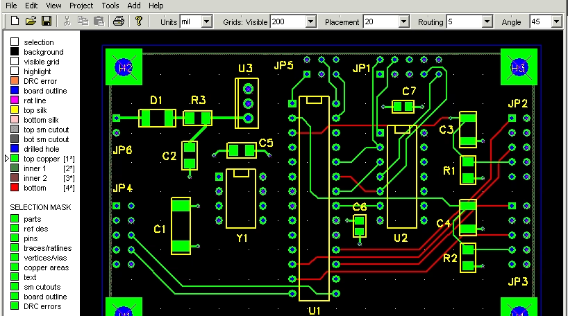
Designing a good LED PCB requires a solid understanding of both electrical and thermal engineering. The main challenge is that the board must carry higher currents and, as a result, manage much more heat than a standard board. The foundation of any design rests on three main factors.
- Thermal Management: LEDs turn electricity into light, but they also turn a significant part of it into heat. If this heat is not removed effectively, the temperature of the LED’s internal junction rises. This leads to lower light output, a shift in color, and can eventually destroy the LED. Managing heat is the single most important factor for LED life and reliability.
- Current Distribution: LEDs are current-driven devices. Their brightness is directly linked to the amount of current flowing through them. The PCB design must ensure that every LED gets the exact same current. This is especially important in parallel circuits. It requires careful calculation of trace widths and good placement of constant-current driver circuits to avoid uneven brightness.
- Power Design: A single LED typically needs a low voltage, around 2 to 4 volts. However, to meet higher voltage or power needs, LEDs are often connected in series or parallel strings. The PCB’s power design must convert the input voltage, like 12V, 24V, or AC mains power, into the right voltage and a constant current for the LED string.
Several professional PCB design software tools are available. For example, Altium Designer is very powerful. Eagle and DipTrace are good for smaller teams or hobbyists. KiCad is a free and open-source option. Mentor Graphics PADS is used for high-performance designs. Picking the right tool helps make the design process more efficient and accurate.
4. Advantages and Disadvantages of LED PCBs
4.1Advantages
- High Energy Efficiency: LEDs themselves are much more efficient than older lighting types. A well-designed LED PCB adds to this by reducing power loss in the circuits. Good heat sinking also keeps the LEDs working at their best temperature.
- Compact and Flexible Design: PCB technology makes it possible to put LEDs and their circuits into very small spaces. Flexible PCBs let designers bend light into shapes that were not possible before.
- Long Operating Life: With good thermal design, an LED PCB module can last much longer than a traditional light bulb. This means less maintenance and lower replacement costs.
- Good Durability: PCBs are mechanically strong. They resist shock and vibration well. This makes them good for tough environments like vehicles or industrial machines.
- Scalability: LED PCB designs can be easily scaled. You can make a tiny indicator light or a huge lighting panel by changing the design, but the basic principles stay the same.
4.2 Disadvantages
- Thermal Management Challenge: For high-power designs, getting rid of the heat is the hardest part. If the thermal design is not done right, the product will fail.
- Manufacturing Cost: Using high-performance materials like metal cores and complex multi-layer designs costs much more than simple single-sided FR-4 boards.
- Difficult to Repair: Modern LED PCBs mostly use tiny surface-mount (SMD) parts packed closely together. If one LED fails, it is very hard to replace. Often, the whole PCB module must be changed.
- Sensitive to Current: LEDs are sensitive to changes in current. They need precise driver circuits. This adds complexity to the power supply design compared to just connecting a voltage source.
5. How to Design an LED Circuit Board?
5.1 LED PCB Schematic Diagram Design

The schematic is the plan for the whole circuit. In this stage, the designer uses EDA tools to draw the electrical connections. The key points are:
- Choose the Driver Type: Decide whether to use a constant-current driver chip or simple current-limiting resistors. For high-power applications or where consistent brightness is critical, a constant-current driver is necessary.
- Calculate Key Values: Based on the LED’s forward voltage (Vf) and operating current (If), calculate the value of series resistors or set up the parts around the driver chip. Make sure all electrical connections are correct and no pins are left unconnected.
- Keep it Clear and Modular: Keep the schematic easy to read. Group different functional blocks, like the power input, driver circuit, and LED array, in separate areas. This makes checking and changing the design easier later.
5.2 LED PCB Layout
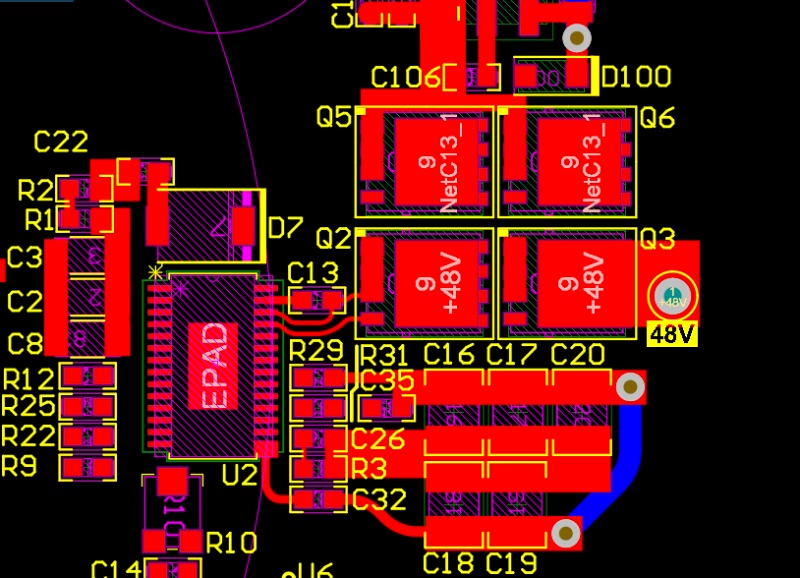
Layout is the step where the plan on paper becomes a physical reality. This stage has a big impact on heat dissipation and electrical performance. Key strategies include:
- LED Symmetry and Spacing: Place the LED array symmetrically around the center of the PCB. This is not just for looks. It helps make the electrical path and the heat path from the driver to each LED as similar as possible. This reduces differences in current and temperature. The space between LEDs depends on optical and thermal needs.
- Place Driver IC Close to LEDs: Keep the traces from the driver IC to the LEDs as short as possible. This cuts down on trace resistance, voltage drop, and power loss. It makes the whole system more stable.
- Placing High-Power Parts: You can group heat sources together. This makes cooling them in one spot easier but can create a hot spot. Or you can spread them out. This spreads the heat more evenly but may raise the overall temperature of the whole board. The choice depends on your cooling method and mechanical design.
- Position Thermal Pads Correctly: High-power LEDs and driver ICs often have a thermal pad on the bottom. This pad must line up with the cooling area on the PCB, like a large copper area or a grid of thermal vias. If it does not, heat cannot flow into the PCB effectively.
5.3 LED PCB Wiring
Wiring means creating the electrical traces that connect the parts. For LED PCBs, follow these main rules:
- Shortest Current Loop Rule: The path the current takes to go out and come back should be as short and direct as possible. A big loop area creates more electrical problems, like interference and voltage spikes.
- Route Power Traces as Pairs: Run the main power supply traces, like VLED+ and GND, close together and parallel to each other. Their magnetic fields cancel out, which lowers the inductance in the loop.
- Avoid Detours: The path from the power source to the first LED, and from the last LED back to the driver, must be straight and short. Any extra bends add resistance and cause a voltage drop.
- Main Trunk and Branch Supply: A good method is to use a low-impedance main trunk and then symmetric branches. First, make a wide, low-resistance copper trace for the main power line. Then, connect each parallel LED branch to this main line in exactly the same way. This helps match the impedance and makes sure the current is shared evenly.
- Wiring for Series and Parallel:
Series: Focus on making sure the voltage drop is even across each LED. Use short traces of the same width to connect them one after another.
Parallel: This is critical. All parallel branches from the power supply point to the LED loads must have exactly the same trace length, shape, and number of vias. This matches the resistance and prevents some LEDs from drawing more current than others.
5.4 LED PCB Power Design and Analysis
The power design affects the efficiency and stability of the whole system.
- Pick the Power Architecture: Based on the input voltage and the voltage needed for the LED string, choose the right circuit type. This could be a buck converter to step voltage down, a boost converter to step it up, or another topology. For multi-channel RGB lights, each color needs its own constant-current driver.
- Trace Width for Current: You must calculate and design wide enough traces based on how much current they will carry. You can use the IPC-2221 standard or online calculators. For example, on a PCB with 1oz copper, a trace might need to be 2mm wide or more to safely carry 2 amps.
- Power and Ground Planes: In multi-layer boards, using whole layers for power and ground gives a very low-resistance path for high currents. It also helps reduce electrical noise.
- Decoupling Capacitors: Place small capacitors close to the power pins of the driver IC. These filter out noise from the power supply and help the chip work smoothly.
5.5 LED PCB Signal Integrity Analysis
For LED applications with PWM dimming, digital addressing like RGB LEDs, or high-speed communication, keeping signals clean is vital.
- Avoid Signal Interference: Keep sensitive signal traces, like PWM control lines, separate from high-current power traces. Do not run them parallel to each other. This stops noise from jumping from one trace to another.
- Simulate and Analyze: Use specialized software tools to simulate the circuit. Check if signals have problems like reflections, overshoot, or ringing during transmission. Make sure the signal shape is clean during fast switching. This prevents LEDs from flickering or causing radio interference.
- Use a Good Ground System: A solid ground system gives signals a clean, low-resistance path to return to their source. This is a basic requirement for good signal integrity.
6. LED Circuit Board Design Considerations
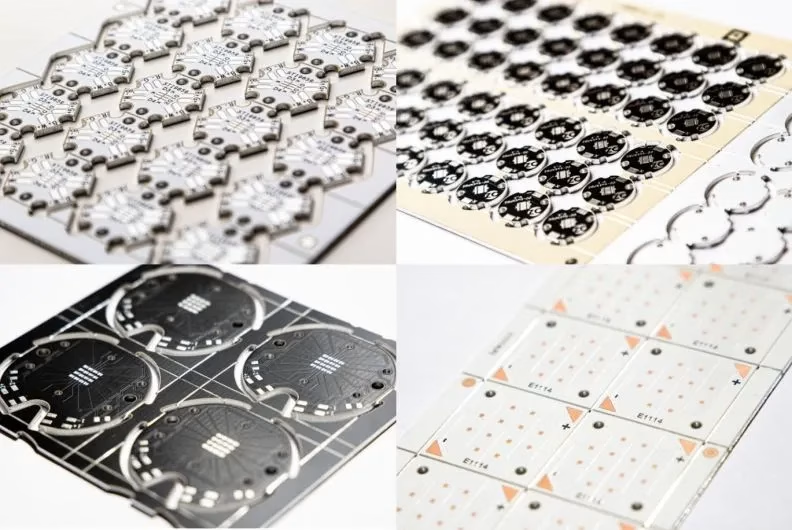
When you design an LED circuit board, you need to think about several things at the same time:
- Board Shape and Size: The PCB’s shape, whether round, rectangular, or custom, must fit exactly into the final product’s mechanical design. For example, an LED strip needs a long, narrow shape. A compact device needs a design that uses space very efficiently.
- Thermal Management Strategy: You must make thermal management a top priority from the start. Besides choosing an MCPCB, design techniques include: using large copper areas as heat spreaders, placing grids of thermal vias under LEDs to pull heat to the other side, and adding external heat sinks or fans if needed.
- Current Control: Make sure every LED or LED string has a precise way to control its current. This could be a simple resistor for low-power uses, or a complex constant-current driver IC for high-power or precise applications.
- Material Choice: Besides the base board material, the thermal insulation layer’s performance matters a lot. Its thermal conductivity is measured in W/m.k. Common values are 1.0, 1.5, 2.0, or even 3.0 W/m.k. Higher numbers mean better heat transfer but also higher cost. The solder mask design also affects cooling. Leaving more of the copper exposed can help radiate heat.
- Electromagnetic Compatibility: Use design rules to control EMI. Keep current loops small, use shielded components if needed, and arrange the layout carefully. This ensures your product does not interfere with other electronics nearby.
7. PCB LED Assembly Methods: Through-Hole vs. SMD
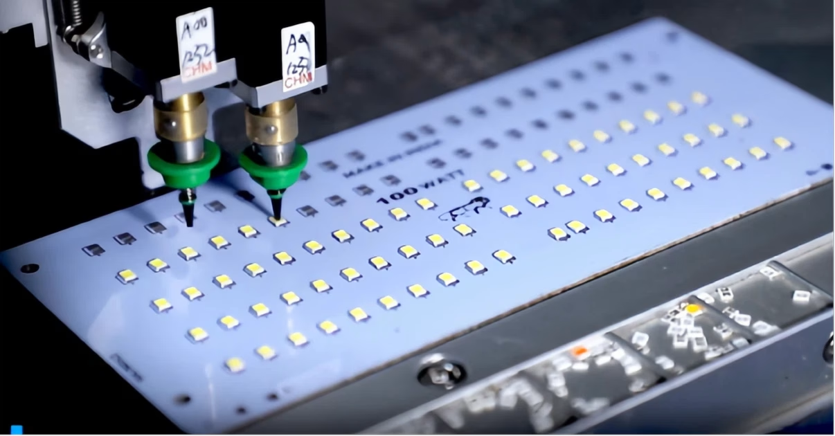
There are two main ways to attach LEDs to a PCB.
- Through-Hole Assembly: LEDs with long wire leads are inserted into holes drilled through the PCB. The leads are then soldered on the other side, often using wave soldering or by hand.
- Surface-Mount Assembly (SMD): Tiny LEDs with small contacts on their body are placed directly onto solder paste on the PCB pads. The whole board is then heated in a reflow oven, which melts the solder and forms all the connections at once.
(1) Advantages of SMD Assembly
Miniaturization: SMD LEDs are very small. They can be placed close together. This is the only way to make very compact designs.
Design Flexibility: SMDs allow for complex circuits and finer optical control.
Better Performance: SMD LEDs often have lower thermal resistance. This helps with heat dissipation.
Good for Automation: SMT assembly is fast and efficient. It is ideal for large production runs and can lower the cost per board.
- Advantages of Through-Hole Assembly (Still Useful For)
Prototyping and Hand Soldering: For hobbyists, DIY projects, or small prototype runs, through-hole parts are much easier to work with by hand.
Very High Mechanical Strength: In some specific applications with extreme vibration or shock, like certain military or aerospace equipment, the strong physical connection of a through-hole part is still an advantage.
8. FAQs
(1) How important are vias for heat transfer? How should I design them?
For double-sided or multi-layer PCBs, vias are the key path for heat to move from the top layer, where the LED is, to a bottom layer or heatsink. Design them in a grid pattern directly under the heat source. The hole size and the thickness of the copper plating inside the hole affect how well they work. For MCPCBs, the thermal insulation layer is usually the main limit on heat flow, not the vias.
(2) Can the insulation layer in an MCPCB fail at high temperatures?
Yes, the insulation layer is often the thermal bottleneck in an MCPCB. Standard organic resin materials have a glass transition temperature (Tg) around 130°C. Working above this temperature for a long time can make the insulation layer degrade, losing its insulating and thermal properties. Choosing a high-temperature, high-performance insulation material is very important.
(3) Can you make a “sinkpad” structure with an aluminum-based MCPCB?
With current technology, a sinkpad structure, where a raised platform is etched for the LED, is usually only done with a copper core. The chemical etching process used to create the raised pad is very hard to control with aluminum. It leads to high failure rates and high costs, often making it more expensive than just using a copper core board.
9. Summary
Designing an LED PCB is a precise process that blends thermal, electrical, and mechanical engineering. Success comes down to three key ideas: focus on heat by planning thermal paths from the start, ensure even current through symmetric layouts with low-resistance traces, and maintain electrical integrity by keeping current paths short. Whether for a simple indicator or a high-power module, balancing these factors is the key to a reliable LED product.
OrinewPCB has focused as a one-stop PCB assembly manufacturer from PCB Manufacturing to Electronic Components Sourcing to PCB Assembly to Test to Program IC for more than 14 Years with reliable quality and fastest delivery for global clients.








