
A Complete Guide to Capacitors in PCB Design

Table of Content
- 1. Apa Itu Kapasitor PCB?
- 2. Bagaimana Cara Kerja Kapasitor PCB?
- 3. Apa saja fungsi kapasitor PCB?
- 4.Apa Saja Jenis-Jenis Kapasitor PCB?
- 5.Pentingnya Kapasitor dalam Desain PCB
- 6. Bagaimana Cara Memilih Kapasitor PCB untuk Desain Anda?
- 7.Penanganan Kapasitor PCB yang Aman
- 8.Pertanyaan Umum Demo Slot
- 9.Kesimpulan
Capacitors are among the most fundamental passive components in electronic circuit design, playing a critical role in the performance, stability, and reliability of printed circuit boards (PCBs). From power integrity and signal conditioning to noise suppression and timing control, capacitors enable modern electronics to function as intended. Whether you are designing a simple analog circuit, a high-speed digital system, or a mixed-signal PCB, a deep understanding of capacitor types, characteristics, and application principles is essential.
This guide provides a comprehensive overview of capacitors in PCB design, tailored for engineers, researchers, and students. We will explore the working principles, classifications, selection criteria, and practical handling guidelines to help you make informed design decisions and avoid common pitfalls.
1. What Is a PCB Capacitor?
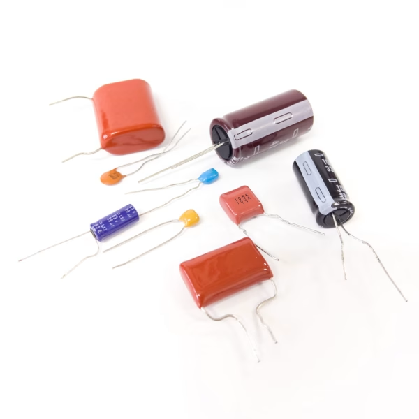
A PCB capacitor is fundamentally a two-terminal electronic component that stores electrical energy in an electrostatic field between its conductive plates. Unlike batteries which store energy through electrochemical reactions, capacitors store energy through charge separation—a purely physical process that enables much faster charge and discharge cycles.
The basic capacitor structure consists of two conducting electrodes separated by a dielectric (insulating) material. When integrated into a PCB, these electrodes connect to copper traces that form part of the circuit topology. The dielectric material—which can range from ceramic and polymer films to electrolytic solutions and specialized oxides—determines many of the capacitor’s key characteristics including its capacitance stability, voltage rating, temperature behavior, and frequency response.
In practical PCB implementation, capacitors exist in two forms: discrete components that are mounted on the board surface or through holes, and distributed capacitive elements inherent in the board structure itself. The latter includes interplane capacitance between power and ground planes, as well as parasitic capacitance between adjacent traces. Understanding both intentional and parasitic capacitive elements is essential for successful high-speed design.
2. How Do PCB Capacitors Work?

The operation of a capacitor is based on electrostatic principles that have been understood for centuries but remain profoundly important in modern electronics. When a voltage potential is applied across a capacitor’s terminals, electrons accumulate on the plate connected to the negative terminal while being depleted from the positive plate. This charge separation creates an electric field across the dielectric material, with energy stored in this field.
The fundamental relationship governing capacitor behavior is expressed as:
C = εA/d
Where:
- Crepresents capacitance in farads (F)
- εis the permittivity of the dielectric material (F/m)
- Ais the overlapping area of the conductive plates (m²)
- dis the separation distance between plates (m)
This relationship explains why capacitors with higher surface area, thinner dielectrics, or materials with higher permittivity exhibit greater capacitance for a given physical size.
3. What Are the Functions of PCB Capacitors?

Capacitors serve multiple roles in electronic circuits, including:
- Decoupling/Bypassing: Provide local energy storage to suppress power supply noise and transient currents.
- Filtering: Remove unwanted frequency components (e.g., ripple in power supplies, noise in signal paths).
- Coupling: Allow AC signals to pass between circuit stages while blocking DC offset.
- Timing: Used with resistors to create RC time constants for oscillators, delays, and pulse shaping.
- Energy Storage: Temporarily hold energy for backup power, peak load support, or pulse discharge.
- Voltage Stabilization: Smooth voltage fluctuations and maintain stable supply rails.
4.What Are the Types of PCB Capacitors?

Capacitors are classified based on dielectric material, construction, and electrical characteristics. The most common types used in PCB design are:
| Type | Dielectric Material | Capacitance Range | Voltage Rating | Advantages | Disadvantages | Primary Applications |
| Ceramic Capacitors (MLCC) | Ceramic (e.g., X7R, COG) | 0.5 pF to 100 µF | 6.3 V to several kV | Small size, low ESR, non-polarized, cost-effective | Limited high-capacitance
options (compared to electrolytic) |
High-frequency decoupling, filtering, RF circuits |
| Aluminum Electrolytic Capacitors | Aluminum oxide with electrolyte | 1 µF to 100,000 µF | 4 V to 500 V | High capacitance
/volume ratio, affordable |
Polarized, limited lifespan, higher ESR | Power supply filtering, bulk energy storage |
| Tantalum Capacitors | Tantalum pentoxide | 0.1 µF to 1000 µF | 2.5 V to 50 V | Stable capacitance, small size, low leakage | Polarized, sensitive to voltage spikes, expensive | Decoupling in compact devices, medical electronics |
| Film Capacitors | Plastic films (polyester, polypropylene, PTFE, etc.) | 100 pF to 100 µF | 50 V to 2 kV | Non-polarized, low distortion, high reliability | Larger physical size | Audio circuits, snubber networks, high-voltage filtering |
| Supercapacitors | Electrochemical double-layer | 0.1 F to several thousand farads | 2.5 V to 5.5 V (higher in series) | Extremely high energy density, rapid charge/discharge | Low voltage per cell, high self-discharge rate | Energy harvesting, backup power, motor startup |
Table Notes:
- Polarity:A key characteristic of capacitors. “Polarized” means the positive and negative terminals must be correctly identified during installation, as reverse connection may cause failure.
- ESR:Stands for Equivalent Series Resistance. A lower ESR typically indicates better performance, especially in high-frequency and power applications.
- Applications:Listed are typical examples; actual applications may be more extensive.
5.The Importance of Capacitors in PCB Design
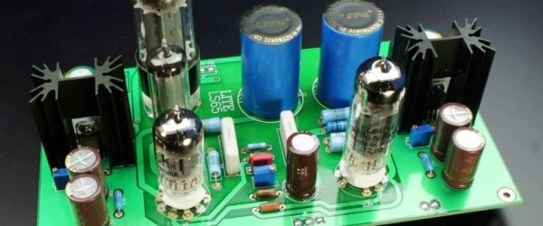
Capacitors are not merely auxiliary components; they are enablers of signal integrity, power integrity, and electromagnetic compatibility (EMC). Their importance manifests in:
- Power Integrity: Decoupling capacitors maintain stable voltage levels by supplying transient currents to ICs, reducing ground bounce and supply droop.
- Signal Integrity: They filter out high-frequency noise, reduce crosstalk, and shape signal edges.
- Timing Accuracy: In oscillators and clock circuits, capacitors define frequency and pulse width with precision.
- Reliability: Proper capacitor selection reduces thermal stress, voltage overshoot, and aging effects.
- Miniaturization: Advanced MLCCs allow high capacitance in tiny packages, enabling compact PCB designs.
Without appropriate capacitor usage, circuits may suffer from oscillations, noise coupling, reset failures, or even permanent damage.
6.How to Select PCB Capacitors for Your Design?

Selecting the appropriate capacitors requires evaluating multiple parameters. Below are the key considerations to guide your selection:
6.1 Capacitance Value
Determine the value based on target impedance, filter cutoff frequency, or energy storage requirements. Note: Ceramic capacitors can experience a significant reduction in actual capacitance under DC bias voltage. Always review the derating curves in the datasheet to ensure adequate capacitance at the intended operating voltage.
6.2 Voltage Rating
Select a capacitor with a rated voltage at least 1.5 times the maximum operating voltage to accommodate transient spikes. For noisy environments (e.g., switching power supplies, motor drives), a safety margin of 2 times or higher is recommended.
6.3 Temperature Coefficient
For stable performance across a wide temperature range (e.g., precision oscillators, filtering circuits), use C0G (NP0) ceramic or film capacitors. For general decoupling, common materials such as X7R or X5R offer a more cost-effective solution.
6.4 Equivalent Series Resistance (ESR)
Low ESR is essential for high-frequency decoupling and power rail filtering to minimize losses and noise. However, certain switching regulator control loops may require a specific ESR range for stability—check the regulator’s datasheet for requirements.
6.5 Polarity
Polarized capacitors (e.g., aluminum electrolytic, tantalum) should only be used in circuits with a guaranteed DC bias, such as power supply filtering or DC-blocking coupling applications. Caution: Reverse voltage or overvoltage can cause catastrophic failure.
6.6 Size and Package
Small SMD packages (e.g., 0402, 0603) save board space, while larger packages (e.g., 1210) often provide better performance with lower ESL/ESR and higher voltage ratings. Through-hole packages offer higher mechanical strength and better thermal characteristics.
6.7 Tolerance
Circuits requiring precision, such as timing, voltage reference, or analog filtering, need tight-tolerance capacitors (±1% to ±5%). For decoupling and bulk storage, wider tolerances (±10% to ±20%) are acceptable and help reduce cost.
6.8 Dielectric Material
The dielectric defines key behaviors. Class 2 materials (e.g., X7R, X5R) exhibit substantial variation in capacitance with voltage and temperature. Class 1 materials (e.g., C0G) are extremely stable but offer lower capacitance density. Electrolytic capacitors provide high capacitance but have limited lifetime.
6.9 Cost and Availability
Balance electrical and reliability requirements with budget constraints. Avoid single-source or end-of-life parts. Prioritize widely available, standard series to ensure supply chain stability.
6.10 Final Recommendation
Validate your selection with SPICE simulations and PDN (Power Distribution Network) analysis tools. Always study the manufacturer’s datasheets carefully, particularly the characteristic graphs (capacitance vs. voltage, ESR vs. frequency, impedance profiles), to make an informed and reliable choice.
7.Safe Handling of PCB Capacitors
Capacitors can pose electrical, thermal, and chemical hazards if mishandled. Follow these guidelines:
7.1 Risks
- Electric Shock: High-voltage capacitors can retain a dangerous charge long after the power has been disconnected. This stored energy can deliver a severe or even lethal shock.
- Thermal Runaway: Applying overvoltage or incorrect reverse polarity can cause excessive internal heating. This may lead to thermal runaway, resulting in venting, rupture, or explosion.
- Chemical Exposure: Electrolytic capacitors contain corrosive liquid or gel electrolytes. If the casing is compromised, these materials can leak and cause burns or damage to equipment and skin.
7.2 Handling Practices
- Always discharge capacitorsbefore touching terminals or circuitry. Use a properly rated bleeder resistor or an insulated shorting tool designed for this purpose.
- Wear appropriate ESD (Electrostatic Discharge) protection, such as a wrist strap and grounded mat, when handling static-sensitive capacitors to prevent damage from electrostatic discharge.
- Carefully observe polarity markings(e.g., “+” and “–” signs) on electrolytic capacitors to prevent reverse installation, which can lead to catastrophic failure.
- Avoid mechanical stresson capacitor leads or terminations. Do not bend leads excessively or subject the capacitor body to pressure, as this can cause internal damage or break the seal.
- For long-term storage, place components in moisture-barrier bagsalong with humidity indicator cards. Store them in a cool, dry environment to prevent degradation.
7.3 Disposal
- Always follow local environmental regulationsregarding the disposal of electronic waste (e-waste). Capacitors are classified as e-waste and should not be discarded with general trash.
- Recycle capacitorswhere possible through approved electronics recycling programs.
- Never incineratecapacitors, as their internal materials can release toxic fumes and harmful substances when burned.
By adhering to these practices, you can minimize risks to personnel and equipment while ensuring the reliable and safe operation of capacitors.
8.FAQs
To minimize parasitic inductance in the power delivery path, ensuring rapid transient response and reducing noise coupling.
Yes, if the capacitance, voltage, ESR, and temperature characteristics meet the circuit requirements. Note that ceramics may have DC bias capacitance reduction.
The frequency at which the capacitor’s parasitic inductance resonates with its capacitance, beyond which it behaves inductively.
Dielectric degradation over time, especially in ceramics (Class II) and electrolytics (electrolyte evaporation).
Yes, ceramic capacitors are non-polarized and can be placed in any orientation.
Overvoltage, reverse bias, or high ripple current can cause thermal runaway, leading to short circuits or ignition.
Use low-ESR, low-inductance capacitors (e.g., high-frequency MLCCs) and consider SRF above your operating frequency.
9.Conclusion
Capacitors are vital to the success of any PCB design, influencing power delivery, signal integrity, timing, and overall system reliability. By understanding their working principles, characteristics, and application guidelines, engineers and designers can optimize circuit performance and avoid common failures.
Key takeaways:
- Choose capacitors based on electrical requirements, environmental conditions, and physical constraints.
- Always consider parasitics (ESR, ESL) in high-frequency designs.
- Follow safe handling and installation practices to ensure longevity and safety.
- Leverage simulation and prototyping to validate capacitor selection before mass production.
With careful selection and implementation, capacitors will serve as reliable, high-performance components in your electronic systems.








