PCB Sensors: A Complete Guide to Types, Design,and Manufacturing

In modern electronic devices, sensors are everywhere. Smartphones sense your touch and orientation. Cars detect tire pressure. Smartwatches monitor heart rate and movement. All these functions rely on a core component: the PCB sensor.
A PCB sensor is a module that integrates sensing elements directly onto a printed circuit board. It allows electronic devices to sense physical parameters such as temperature, pressure, motion, humidity, and gas concentration, and then converts this information into electrical signals for the processor to analyze. This article provides a systematic introduction to PCB sensors, including their definition, types, applications, design process, manufacturing challenges, and frequently asked questions. It aims to help engineers and technicians fully understand this key technology.
1. What Is a PCB Sensor?

A PCB sensor is a module that integrates sensing elements, signal conditioning circuits, an analog-to-digital converter (ADC), and communication interfaces on a single circuit board. It can not only detect environmental changes but also convert the measured physical quantities into electrical signals for a microcontroller or host computer to process.
Simply put, a PCB sensor is “a circuit board that gives electronic devices the ability to sense.”
Key Components of a PCB Sensor Board
A complete PCB sensor board typically contains the following six core parts:
(1) Sensing Element
This is the heart of the sensor. It directly detects physical parameters such as temperature, pressure, light intensity, or gas concentration. Different types of sensors use different sensitive materials or structures, such as thermistors, piezoelectric crystals, or photodiodes.
(2) Signal Conditioning Circuitry
The output from the sensing element is often very weak and may contain noise. Signal conditioning circuitry amplifies, filters, and linearizes the raw signal to make it suitable for digitization. Common conditioning circuits include operational amplifiers, filters, and comparators.
(3)Analog-to-Digital Converter (ADC)
Most microcontrollers can only process digital signals. The ADC converts a continuously changing analog voltage signal into discrete digital values for the processor to read. The accuracy of the ADC (such as 8-bit, 12-bit, or 16-bit) directly affects the measurement resolution of the sensor.
(4)Interface to Microcontroller or Processor
The digitized signal is sent to a microcontroller (MCU) or processor for decoding, calculation, and logic decision-making. The MCU can trigger actions based on the sensor data, such as alarms, display updates, or data transmission.
(5) Power Supply and Regulation
Sensors, ADCs, and other components need stable, low-noise voltage to operate. The power supply module typically includes an LDO (low-dropout linear regulator) or a DC-DC converter to ensure stable operation when the battery or external power fluctuates.
(6) Communication Interface
The sensor board needs to output data to external systems. Common interfaces include I²C, SPI, UART, CAN, and even wireless modules such as BLE or Wi-Fi.
2. Types of PCB Sensors
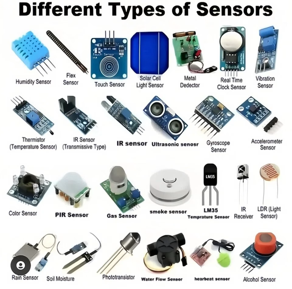
Based on the physical parameters they detect, PCB sensors can be divided into the following seven major categories.
2.1 Temperature Sensors
How they work: Measure temperature by detecting changes in resistance or voltage of a sensing element.
- Thermistor: Resistance changes significantly with temperature. Fast response, high accuracy. Commonly used in thermometers and battery pack monitoring.
- Thermocouple: Two different metals produce a voltage proportional to the temperature difference. Suitable for high-temperature industrial measurements such as furnace control.
- RTD (Resistance Temperature Detector): Uses metals like platinum. Resistance changes linearly with temperature. High accuracy but higher cost.
Typical applications: CPU temperature monitoring, HVAC systems, refrigerator temperature control, wearable body temperature detection.
2.2 Pressure Sensors
How they work: Convert gas or liquid pressure into electrical signals.
- Piezoelectric: Uses the piezoelectric effect to convert pressure into charge or voltage. Used for dynamic pressure measurement such as engine knock detection.
- Capacitive: Pressure deforms a diaphragm, changing the capacitance value. High accuracy and low power consumption. Widely used in tire pressure monitoring systems (TPMS) and medical ventilators.
- Resistive: Pressure changes the resistance of a strain gauge. Lower cost. Suitable for electronic scales and touch screens.
Typical applications: Automotive tire pressure monitoring, industrial process control, medical devices (blood pressure monitors), household water purifiers.
2.3 Motion and Acceleration Sensors
How they work: Based on MEMS (Micro-Electro-Mechanical Systems) technology, detect linear acceleration or angular velocity.
- Accelerometer: Measures linear acceleration along the X, Y, and Z axes. Can determine tilt, vibration, or impact. Common in smartphone screen rotation and pedometers.
- Gyroscope: Measures angular velocity (rotation rate). Used for navigation, image stabilization, and drone attitude control.
- IMU (Inertial Measurement Unit): Combines an accelerometer and a gyroscope. Used in robots, VR devices, and vehicle stability systems.
Typical applications: Smartphone orientation detection, game controllers, drone flight control, fitness trackers.
2.4 Gas and Chemical Sensors
How they work: Detect gases through chemical reactions or physical adsorption between a sensitive material and the target gas, changing resistance or capacitance.
- Electrochemical: Detects toxic gases such as CO and NO₂. High accuracy but limited lifetime. Used in industrial safety.
- Metal Oxide Semiconductor (MOS): Detects flammable gases (methane, hydrogen) or air quality (VOC). Low cost. Commonly used in smart home air quality monitoring.
- NDIR (Non-Dispersive Infrared): Uses the absorption of infrared light by specific gases to measure CO₂ concentration. High accuracy and long life.
Typical applications: Mine gas alarms, indoor air quality monitoring, automotive exhaust detection, smart refrigerators.
2.5 Humidity Sensors
How they work: When a moisture-sensitive material (such as a polymer film) absorbs or releases water vapor, its dielectric constant or resistance changes.
- Capacitive humidity sensor: Humidity changes the dielectric constant of a polymer film, thereby changing the capacitance value. Good linearity and small hysteresis. The mainstream type.
- Resistive humidity sensor: Humidity changes the resistance of a conductive polymer or ceramic. Lower cost but slightly poorer stability.
Typical applications: Weather stations, agricultural greenhouses, air conditioning systems, dehumidifiers, pharmaceutical storage monitoring.
2.6 Light Sensors
How they work: Use the photoelectric effect to convert light intensity into current or voltage.
- Photodiode: Fast response, good linearity. Used for ambient light detection and fiber optic communication.
- Phototransistor: Higher sensitivity, suitable for low-light detection such as automatic night lights and security devices.
- Ambient Light Sensor (ALS): Integrates an optical filter to mimic the human eye response. Used for automatic screen brightness adjustment.
Typical applications: Smartphone automatic screen dimming, solar tracking systems, smart streetlights, camera exposure control.
2.7 Touch and Proximity Sensors
How they work: Detect changes in capacitance, inductance, or infrared light between the sensor and an object.
- Capacitive touch sensor: A finger approaching changes the capacitance between electrodes. Used for touch buttons and touchscreens.
- Infrared proximity sensor: Emits infrared light and detects the intensity of reflected light. Used to detect if an object is approaching (such as turning off the screen during a phone call).
- Inductive proximity sensor: Detects inductance changes when a metal object approaches. Used for position detection in industrial applications.
Typical applications: Smartphone touchscreens, smart home appliance touch panels, automatic faucets, industrial limit switches.
3. Applications of PCB Sensors
PCB sensors are used in almost all electronic devices. The table below shows six main application areas and their typical scenarios.
| Application Area | Key Applications | Common Sensor Types |
| Consumer Electronics | Smartphones, wearables, game consoles | Accelerometer, gyroscope, ambient light, proximity, heart rate, SpO₂ |
| Industrial Automation | Process control, machine health monitoring, robotics | Pressure, flow, level, vibration, temperature, proximity switch, encoder |
| Automotive Electronics | Engine control, safety systems, ADAS | Pressure, temperature, oxygen sensor, TPMS, airbag accelerometer, radar, ultrasonic |
| IoT and Smart Home | Environmental monitoring, smart security, energy saving | Temperature/humidity, light, VOC/CO₂, PIR motion, door/window, leak detection |
| Medical Devices | Vital signs monitoring, diagnostic equipment | ECG electrode, SpO₂ probe, temperature, biosensor, flow sensor |
| Environment and Agritech | Weather monitoring, water quality analysis, precision irrigation | Soil moisture, pH, dissolved oxygen, light radiation, barometric pressure, ammonia, hydrogen sulfide |
4. How to Build a PCB Sensor Module: Step-by-Step Explanation
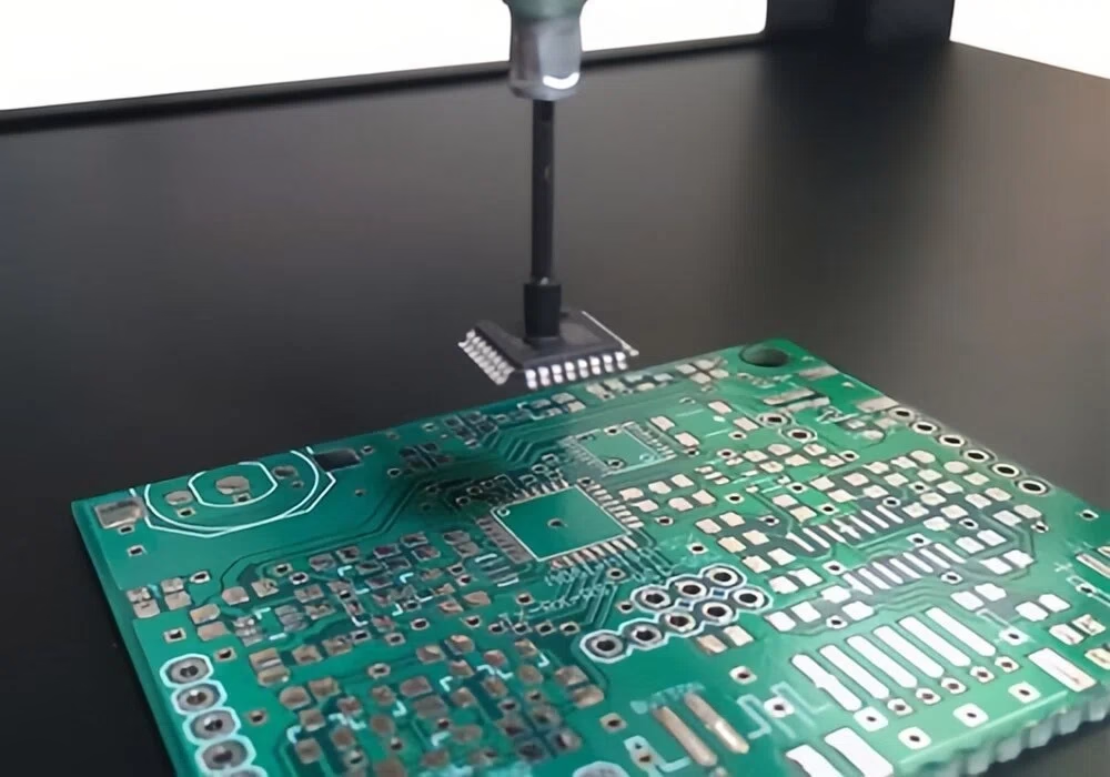
Building a reliable PCB sensor module requires seven key steps.
4.1 Define Requirements
Before drawing any circuits, clearly define the following:
- What parameter will be measured? Temperature? Pressure? Motion?
- Range and accuracy: What measurement range is needed? What error is allowed?
- Resolution: The smallest detectable change (e.g., 0.1°C or 0.01°C)?
- Response time: How quickly does the data need to be updated?
- Environmental conditions: Operating temperature range, humidity, vibration, or corrosive gases?
- Mechanical constraints: Board size, shape, and mounting method.
- Power supply: Battery-powered or external power? Voltage range?
- Communication interface: I²C, SPI, UART, or wireless?
4.2 Choose the Right Type of Sensor
Select the sensor based on the requirements from the first step. Key indicators to consider include:
- Sensitivity:How much the output signal changes with the measured physical quantity.
- Linearity:Whether the output is proportional to the input.
- Power consumption: Critical for battery-powered devices.
- Interface type:Analog output or digital output (such as I²C)?
- Package and size: Suitable for your PCB layout?
- Cost and availability: Within budget? Easy to source?
4.3 Schematic Design
Use an EDA tool (such as Altium Designer, KiCad, or EasyEDA) to draw the schematic. Tasks include:
- Place the sensor chip and its peripheral circuits (such as decoupling capacitors and pull-up resistors).
- Add signal conditioning circuits (amplifiers, filters).
- Add an ADC if the sensor has an analog output.
- Add a microcontroller (if on-board processing is needed) or a connector (to connect to an external MCU).
- Add a power regulation circuit (such as an LDO).
- Add communication interface circuits.
4.4 PCB Layout
When converting the schematic into a physical PCB layout, pay special attention to the following points:
- Grounding design: Use a solid ground plane. Separate analog and digital grounds and connect them at a single point to reduce noise coupling.
- Routing rules: Keep analog signal traces short and straight. Avoid running them parallel to high-speed digital signals. Use differential pairs for differential signals.
- Shielding and isolation: Add a guard ring or shielding can around sensitive analog circuits.
- Thermal management: Place temperature sensors away from heat-generating components (such as voltage regulators and MCUs). If necessary, cut thermal isolation slots in the PCB.
- Decoupling capacitors: Place a 0.1µF ceramic capacitor near the power pin of each IC, as close to the pin as possible.
4.5 Simulation and Prototype
- Circuit simulation: Use tools like SPICE to simulate the frequency response, noise, and stability of the analog front end (amplifiers, filters).
- Signal integrity simulation: Check for reflection and crosstalk on high-speed signals.
- Thermal simulation: Evaluate the temperature distribution on the board to ensure the sensor does not drift due to self-heating.
- Build a prototype: Order a small batch of PCBs, hand-solder or use small-volume pick-and-place, and test in real environments.
4.6 Test and Calibration
- Functional test: Verify that the sensor works correctly across its full range.
- Performance test: Measure accuracy, linearity, repeatability, and response time.
- Environmental test: Test stability under high temperature, high humidity, vibration, and other conditions.
- Calibration: Calibrate the sensor using reference standards (such as a precision temperature bath or pressure calibrator). Store calibration coefficients in on-board EEPROM or the MCU’s Flash memory.
4.7 Mass Production
Once the prototype has been verified, mass production can begin. Prepare the following:
- Production files: Gerber files (for PCB manufacturing), BOM (bill of materials), centroid file (for pick-and-place machines), assembly drawings.
- Test fixtures: Design dedicated ICT (in-circuit test) or FCT (functional test) fixtures for fast batch testing.
- Choose a manufacturer: Select an experienced PCB manufacturer and SMT assembly house to ensure quality, delivery, and traceability.
- Certifications: Prepare CE, FCC, RoHS, and other certifications as required by the target market.
5. Challenges of Integration in PCB Sensors
Integrating sensors onto a PCB is not easy. The table below shows five common challenges and their solutions.
| Challenge | Cause | Solutions |
| Signal Noise | Coupling between digital and analog signals, power ripple, external EMI | Use separate analog ground, add shielding, add filtering circuits, use differential signals |
| Thermal Interference | Heat-generating components (MCU, power chip) affect temperature/pressure sensor accuracy | Thermal simulation, place sensor away from heat sources, cut thermal isolation slots, add ventilation holes |
| Calibration Drift | Sensor ages and drifts over time and temperature | Regular recalibration, store calibration coefficients, design self-calibration routines |
| Miniaturization Pressure | Products demand smaller size, but sensors and circuits take space | Use multilayer PCBs, embedded passives, choose smaller sensor packages (such as WLCSP) |
| Environmental Tolerance | Moisture, corrosion, vibration, and harsh conditions cause failure | Use conformal coating, sealed enclosures, choose industrial-grade or automotive-grade components |
6. FAQs
(1) How can I ensure long-term stability of PCB sensors in harsh environments?
You can take the following measures: use conformal coating to protect the board from moisture and corrosion; choose components with a wide temperature range (such as -40°C to +125°C); add ESD and overvoltage protection circuits; design self-diagnostic functions to regularly check sensor health.
(2) Why is my temperature sensor reading inaccurately?
The most common reason is that the sensor is placed near heat-generating components (such as an MCU or voltage regulator), causing a local hot spot that affects the true environmental temperature reading. Other possible causes include poor ventilation, insufficient thermal isolation on the PCB, sensor aging, or contamination. Solutions: move the sensor away from heat sources or cut thermal isolation slots in the PCB.
(3)What are the main cost drivers for PCB sensors?
Main cost drivers include: 1) Sensor type and complexity (e.g., MEMS sensors and biosensors are more expensive); 2) PCB specifications (layer count, size, use of high-frequency or flexible materials); 3) Cost of high-precision peripheral components; 4) Special processes (such as impedance control and conformal coating); 5) Labor and equipment costs for 100% functional testing and calibration; 6) Industry certification fees (such as automotive AEC-Q100 or medical ISO13485); 7) Order quantity (small-batch unit cost is much higher than large-batch).
(4)How do I choose a PCB sensor manufacturer for my project?
Check the following points: Does the manufacturer have rich experience in sensor PCB manufacturing (especially for your type of sensor)? Does it have quality certifications such as ISO9001 and UL? Does it offer one-stop service from PCB fabrication, component sourcing, to SMT assembly? Does it have testing capabilities such as AOI, X-ray, and ICT? What are customer reviews and after-sales service like?
(5)What are the advantages and disadvantages of analog sensors vs. digital sensors?
Analog sensors output a continuous voltage or current signal. They have lower cost and faster response, but require an external ADC and have weaker noise immunity. Digital sensors have an integrated ADC and calibration circuit, outputting digital values directly (such as via an I²C interface). They are easy to use and have strong noise immunity, but cost more and may have limited sampling rates.
7. Conclusion
PCB sensors are the core bridge that allows electronic devices to perceive the physical world. From temperature and pressure to motion and gas, various types of sensors, integrated with PCBs and signal processing circuits, give devices the ability to sense intelligently.
Building a reliable sensor module requires a complete process: defining requirements, selecting the sensor, designing the schematic, laying out the PCB, prototyping, testing and calibrating, and finally mass production. Key challenges to focus on include signal integrity, thermal management, and noise suppression.
With the rapid development of the Internet of Things, autonomous driving, and smart healthcare, the demand for high-performance, miniaturized, low-power PCB sensors will continue to grow. We hope this article provides clear and practical reference for your sensor PCB projects.