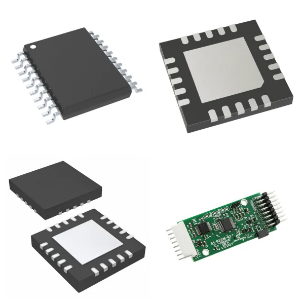
<h1> Touch Screen Controllers </h1> <p> Touch Screen Controllers are the core electronic components of touch screen systems. They are responsible for detecting and processing user touch input signals and passing coordinate data to the main control system (such as a PC or embedded microcontroller) to achieve precise human-computer interaction. Such controllers are usually integrated into touchscreen components or used as independent chips and are widely used in consumer electronics, industrial automation, medical equipment, and other fields. </p> <p> </p> <h2> 1. What are Touch Screen Controllers? </h2> <p> A touchscreen controller is a small microcontroller chip located between a touch sensor (such as a capacitive sensing panel) and the main control system. It is responsible for converting physical touch signals into digital coordinate signals and performing tasks such as signal processing, debouncing, and calibration. It ensures the real-time and accuracy of touch response and supports functions such as multi-touch and gesture recognition. </p> <p> </p> <p> In a capacitive touch screen, the controller determines the touch position by detecting the capacitance change between electrodes (such as self-capacitance or interactive capacitance). The sensitivity can be adjusted by external capacitance to adapt to different environmental requirements. </p> <p> </p> <h2> 2. What are the Working Principles and Technical Characteristics of Touch Screen Controllers? </h2> <p> The controller uses self-correction technology to automatically adapt to environmental changes (such as temperature and humidity drift) without manual intervention; the initialization time is about 200 milliseconds, the sampling cycle is short (such as sampling every 2.8 milliseconds), and the response time is fast (the key detection reaction time is about 18 milliseconds), ensuring the smoothness of high-frequency operations. </p> <p> </p> <p> Key technical indicators include: touch point accuracy (linearity error <2%), multi-touch support (such as 10-point touch), output logic (output low level when touched, output high level when not touched), and communication with the main control system through interfaces such as IIC and SPI. </p> <p> </p> <p> To improve anti-interference ability, the controller often integrates de-jitter processing circuits and can configure sensitivity capacitors (range 5-100pF) to cope with touch scenarios of different media (such as glass or plastic coverings). </p> <p> </p> <h2> 3. What are the Typical Products and Performance Parameters of Touch Screen Controllers? </h2> <p> <strong>General Controller</strong>: such as SC02F chip, supports 2 independent touch sensing buttons, operating voltage range 2.0V~5.5V, packaged as SOP8, suitable for low-cost consumer electronics. Its features include parallel output, automatic compensation for environmental drift, and high compatibility design. </p> <p> <strong>High-performance Controller</strong>: such as GT9147, equipped with multiple sensing channels (such as 10 sensing + 17 driving channels), manages coordinate data through registers and status registers (such as 0X814E), supports complex gesture recognition, and is often used in industrial touch screens. </p> <p> </p> <h2> 4. What are the Application Scenarios and Advantages of Touch Screen Controllers? </h2> <p> In industrial automation (such as 8.4-inch industrial touch screens), the controller provides dustproof, waterproof, and shockproof features to ensure stable operation in harsh environments; combined with wireless communication modules (such as Wi-Fi), remote monitoring and data analysis are achieved. </p> <p> </p> <p> In consumer electronics (such as mobile phones, and tablets) and embedded systems (such as 51 single-chip microcomputers driving TFT touch screens), controllers simplify human-computer interaction design and improve operating efficiency and user experience. </p> <p> </p> <p> In short, as a key hub for human-computer interaction, touch screen controllers integrate microelectronics technology and signal processing algorithms. Their miniaturization, high reliability, and easy integration characteristics drive smart devices to develop in a more intuitive and efficient direction. </p> <p>
<h1> Digital Potentiometers </h1> <h2> 1. What are Digital Potentiometers? </h2> <p> A digital potentiometer (Digipot) is an integrated circuit controlled by digital signals, which is used to simulate the resistance adjustment function of a traditional mechanical potentiometer. It is a CMOS digital-analog mixed signal processing device, which can realize dynamic adjustment of resistance value through microcontroller (such as MCU) programming. </p> <p> </p> <h2> 2. What are the Core Features and Advantages of Digital Potentiometers? </h2> <p> <strong>Digital Control</strong> </p> <p> Receive digital instructions through I²C, SPI, or up/down protocol to accurately adjust the resistance value without mechanical operation. </p> <p> </p> <p> <strong>High Precision and Reliability</strong> </p> <p> The resolution is usually 5-10 bits (32-1024 taps), 8 bits (256 levels) is the most common, and the adjustment accuracy is much higher than that of a mechanical potentiometer. </p> <p> </p> <p> No physical contacts, anti-vibration, anti-interference, long life, and not affected by environmental contamination. </p> <p> <strong>Miniaturization and Integration</strong> </p> <p> Chip-level packaging, small in size, and suitable for high-density circuit design, can be directly integrated into the analog signal processing link. </p> <p> </p> <h2> 3. What is the Internal Structure and Working Principle of Digital Potentiometers? </h2> <p> <strong>1) Resistor Ladder Architecture</strong>: </p> <p> The internal resistor array (Resistor Ladder) is used, and each tap is connected to the output end through a switch. The digital signal controls the tap position and changes the resistance ratio between the A end, the B end, and the wiper. </p> <p> </p> <p> <strong>2) Working Mode</strong>: </p> <p> Potentiometer mode (three terminals: A, B, W): Used as a voltage divider to adjust the output voltage. </p> <p> </p> <p> Rheostat mode (two terminals: A/W or B/W): Used as an adjustable resistor. </p> <p> </p> <h2> 4. What are Digital Potentiometers Used for? </h2> <p> <strong>Signal Conditioning</strong>: Fine-tuning amplifier gain (such as instrument amplifier), offset calibration, and small signal audio balance. </p> <p> <strong>Power Management</strong>: Dynamically adjust the output voltage of the linear regulated power supply. </p> <p> <strong>Dynamic Control Circuit</strong>: Adjust LED dimming current, oscillator frequency/amplitude, filter bandwidth, and differential amplifier gain. </p> <p> <strong>Embedded System</strong>: Replace mechanical potentiometers to realize software control of analog circuits by MCU (such as volume adjustment of smart devices). </p> <p> </p> <h2> 5. What are the Key Technical Parameters and Limitations of Digital Potentiometers? </h2> <p> <strong>Tap Resolution</strong>: 5 bits (32 levels) to 10 bits (1024 levels), 8 bits (256 levels) are the most common </p> <p> <strong>Operating Voltage</strong>: Usually compatible with 3.3V/5V systems (such as MCP42100 supports 2.7V–5.5V) </p> <p> <strong>Current Limit</strong>: Most models ≤1mA (such as MCP4XXXX series), pay attention to load design </p> <p> <strong>Voltage Range Limit</strong>: The input voltage must be within the digital power supply range, and additional circuits are required when it exceeds the range </p> <p> </p> <h2> 6. Comparison with Traditional Mechanical Potentiometers </h2> <table> <tbody> <tr class="firstRow"> <td width="189" valign="top" style="padding: 0px 7px;border-width: 1px;border-color: windowtext"> <p> Features </p> </td> <td width="189" valign="top" style="padding: 0px 7px;border-width: 1px;border-color: windowtext"> <p> Digital Potentiometer </p> </td> <td width="189" valign="top" style="padding: 0px 7px;border-width: 1px;border-color: windowtext"> <p> Mechanical Potentiometer </p> </td> </tr> <tr> <td width="189" valign="top" style="padding: 0px 7px;border-left-width: 1px;border-left-color: windowtext;border-right-width: 1px;border-right-color: windowtext;border-top: none;border-bottom-width: 1px;border-bottom-color: windowtext"> <p> Control Method </p> </td> <td width="189" valign="top" style="padding: 0px 7px;border-left-width: 1px;border-left-color: windowtext;border-right-width: 1px;border-right-color: windowtext;border-top: none;border-bottom-width: 1px;border-bottom-color: windowtext"> <p> Digital signal (MCU/logic circuit) </p> </td> <td width="189" valign="top" style="padding: 0px 7px;border-left-width: 1px;border-left-color: windowtext;border-right-width: 1px;border-right-color: windowtext;border-top: none;border-bottom-width: 1px;border-bottom-color: windowtext"> <p> Manual rotation/sliding </p> </td> </tr> <tr> <td width="189" valign="top" style="padding: 0px 7px;border-left-width: 1px;border-left-color: windowtext;border-right-width: 1px;border-right-color: windowtext;border-top: none;border-bottom-width: 1px;border-bottom-color: windowtext"> <p> Life and Reliability </p> </td> <td width="189" valign="top" style="padding: 0px 7px;border-left-width: 1px;border-left-color: windowtext;border-right-width: 1px;border-right-color: windowtext;border-top: none;border-bottom-width: 1px;border-bottom-color: windowtext"> <p> No mechanical wear, long life </p> </td> <td width="189" valign="top" style="padding: 0px 7px;border-left-width: 1px;border-left-color: windowtext;border-right-width: 1px;border-right-color: windowtext;border-top: none;border-bottom-width: 1px;border-bottom-color: windowtext"> <p> Contacts are prone to oxidation and wear </p> </td> </tr> <tr> <td width="189" valign="top" style="padding: 0px 7px;border-left-width: 1px;border-left-color: windowtext;border-right-width: 1px;border-right-color: windowtext;border-top: none;border-bottom-width: 1px;border-bottom-color: windowtext"> <p> Accuracy </p> </td> <td width="189" valign="top" style="padding: 0px 7px;border-left-width: 1px;border-left-color: windowtext;border-right-width: 1px;border-right-color: windowtext;border-top: none;border-bottom-width: 1px;border-bottom-color: windowtext"> <p> High precision, preset values can be stored </p> </td> <td width="189" valign="top" style="padding: 0px 7px;border-left-width: 1px;border-left-color: windowtext;border-right-width: 1px;border-right-color: windowtext;border-top: none;border-bottom-width: 1px;border-bottom-color: windowtext"> <p> Depends on manual adjustment, easy to introduce errors </p> </td> </tr> <tr> <td width="189" valign="top" style="padding: 0px 7px;border-left-width: 1px;border-left-color: windowtext;border-right-width: 1px;border-right-color: windowtext;border-top: none;border-bottom-width: 1px;border-bottom-color: windowtext"> <p> Environmental Adaptability </p> </td> <td width="189" valign="top" style="padding: 0px 7px;border-left-width: 1px;border-left-color: windowtext;border-right-width: 1px;border-right-color: windowtext;border-top: none;border-bottom-width: 1px;border-bottom-color: windowtext"> <p> Anti-vibration, humidity, temperature changes </p> </td> <td width="189" valign="top" style="padding: 0px 7px;border-left-width: 1px;border-left-color: windowtext;border-right-width: 1px;border-right-color: windowtext;border-top: none;border-bottom-width: 1px;border-bottom-color: windowtext"> <p> Sensitive to physical environment </p> </td> </tr> <tr> <td width="189" valign="top" style="padding: 0px 7px;border-left-width: 1px;border-left-color: windowtext;border-right-width: 1px;border-right-color: windowtext;border-top: none;border-bottom-width: 1px;border-bottom-color: windowtext"> <p> Integration </p> </td> <td width="189" valign="top" style="padding: 0px 7px;border-left-width: 1px;border-left-color: windowtext;border-right-width: 1px;border-right-color: windowtext;border-top: none;border-bottom-width: 1px;border-bottom-color: windowtext"> <p> Easy to integrate with digital systems, support bus control </p> </td> <td width="189" valign="top" style="padding: 0px 7px;border-left-width: 1px;border-left-color: windowtext;border-right-width: 1px;border-right-color: windowtext;border-top: none;border-bottom-width: 1px;border-bottom-color: windowtext"> <p> Independent physical operation required </p> </td> </tr> <tr> <td width="189" valign="top" style="padding: 0px 7px;border-left-width: 1px;border-left-color: windowtext;border-right-width: 1px;border-right-color: windowtext;border-top: none;border-bottom-width: 1px;border-bottom-color: windowtext"> <p> Power Handling </p> </td> <td width="189" valign="top" style="padding: 0px 7px;border-left-width: 1px;border-left-color: windowtext;border-right-width: 1px;border-right-color: windowtext;border-top: none;border-bottom-width: 1px;border-bottom-color: windowtext"> <p> Only suitable for low-power scenarios (usually ≤1W) </p> </td> <td width="189" valign="top" style="padding: 0px 7px;border-left-width: 1px;border-left-color: windowtext;border-right-width: 1px;border-right-color: windowtext;border-top: none;border-bottom-width: 1px;border-bottom-color: windowtext"> <p> Can support higher power </p> </td> </tr> </tbody> </table> <p> </p> <p> </p> <h2> 7. Design Considerations for Digital Potentiometers </h2> <p> <strong>Current and Voltage Limits</strong>: Strictly follow the device specifications to avoid overload damage. </p> <p> <strong>Cascade Expansion</strong>: Some models (such as MCP42100) support multi-module cascading to increase control channels. </p> <p> <strong>Dynamic Response</strong>: The tap switching time can reach microseconds, which is suitable for real-time adjustment scenarios. </p> <p> </p> <p> Digital potentiometers have significantly improved the flexibility and automation level of circuit control through the design concept of "placing analog devices on the bus", and have become an ideal solution to replace mechanical potentiometers in modern electronic systems. </p> <p> </p> <p>
<h1> Analog to Digital Converters (ADC) </h1> <h2> 1. What are Analog to Digital Converters (ADC)? </h2> <p> <strong>Basic Definition</strong> </p> <p> ADC (Analog-to-digital converter) is an electronic device that converts continuously changing analog signals (such as voltage and current) into discrete digital signals (binary code). It builds a bridge between the physical world (analog signal) and digital systems (processors, controllers). </p> <p> </p> <p> <strong>Functional Significance</strong> </p> <p> Digital systems (such as microprocessors) can only process binary signals (0/1), while the analog signals output by physical sensors (temperature, pressure, etc.) need to be converted into digital quantities through ADC before they can be recognized and processed by digital circuits. </p> <p> </p> <h2> 2. How does Analog to Digital Converters (ADC) Work? </h2> <p> <strong>The conversion process of ADC includes four key steps</strong>: </p> <p> <strong>Sampling</strong>: Collect the instantaneous value of the analog signal at fixed time intervals. </p> <p> <strong>Holding</strong>: Hold the sampled value for a short time to ensure signal stability during conversion. </p> <p> <strong>Quantization</strong>: Map the sampled value to a finite discrete level (determined by the resolution). </p> <p> <strong>Encoding</strong>: Convert the quantized value to a binary digital output. </p> <p> </p> <p> For example, a 4-bit ADC divides the analog voltage into 24=16 discrete levels and outputs a 4-bit binary code to represent the relative voltage value. </p> <p> </p> <h2> 3. Key Performance Parameters of Analog to Digital Converters (ADC) </h2> <p> <strong>Resolution</strong> </p> <p> The number of bits of the output digital quantity (such as 8 bits, or 12 bits) determines the minimum resolvable voltage (Vref/(2N−1)). </p> <p> </p> <p> <strong>Sampling Rate </strong> </p> <p> The number of samples per second (Hz), which must meet the Nyquist theorem (twice higher than the highest frequency of the signal). </p> <p> </p> <p> <strong>Reference Voltage </strong> </p> <p> The reference standard for conversion, the output digital quantity represents the ratio of the input signal to the reference voltage. </p> <p> </p> <h2> 4. What are Analog to Digital Converters (ADC) Used for? </h2> <p> <strong>Automotive electronics</strong>: temperature/pressure sensor signal conversion to ECU (electronic control unit). </p> <p> <strong>Medical Equipment</strong>: digital acquisition of physiological signals (such as electrocardiogram, blood pressure). </p> <p> <strong>Industrial Control</strong>: real-time monitoring of analog quantities (flow, displacement) and feedback to digital systems. </p> <p> </p> <h2> 5. What are the Types of Analog to Digital Converters (ADC)? </h2> <p> <strong>ADC types are diverse, including</strong>: </p> <p> <strong>Successive Approximation Register (SAR)</strong> : balance speed and accuracy. </p> <p> <strong>Σ-Δ Type</strong>: high-resolution audio processing. </p> <p> <strong>Pipeline Type</strong>: high-speed communication system. </p> <p> </p> <p> ADC is the core interface device of modern electronic systems, and its performance directly affects the accuracy and efficiency of data acquisition. </p> <p> </p> <h2> 6. Analog to Digital Converters (ADC) FAQs </h2> <h3> 1)How to reduce ADC errors? </h3> <p> Use an external high-stability reference voltage source (instead of an internal reference); </p> <p> Add hardware filtering (such as RC low-pass filtering) to reduce noise; </p> <p> <strong>Optimize PCB layout</strong>: shorten signal routing and keep away from high-frequency interference sources; </p> <p> Software calibration of offset/gain errors. </p> <p> </p> <h3> 2) What to do if the input signal amplitude is too small? </h3> <p> The pre-gain amplifier (PGA) amplifies the signal to the ADC range and improves the effective resolution. </p> <p> </p> <h3> 3) How to avoid interference when acquiring multiple channels? </h3> <p> Configure a reasonable sampling time (allow the signal to stabilize); </p> <p> Use differential input mode to suppress common-mode noise. </p> <p> </p> <h3> 4) How to choose an ADC model? </h3> <p> <strong>Resolution</strong>: The more subtle the change in sensor output, the higher the bit number required (e.g. 12 bits for temperature monitoring, 16 bits or more for audio acquisition); </p> <p> Sampling Rate: Dynamic signals (e.g. audio) require MHz level, and low-speed sensors can be reduced to kSPS35. </p> <p> </p> <h3> 5) What is the performance of the built-in ADC of MCUs such as STM32? </h3> <p> Most of them meet general requirements: 12-bit resolution, 1MSPS sampling rate, support for multi-channel scanning and calibration functions, and better cost performance than external ADC chips. </p> <p>
<h1> Analog Front End (AFE) </h1> <h2> 1. What is Analog Front End (AFE)? </h2> <p> Analog Front End (AFE) is a key component for processing analog signals in electronic systems. It is located between the sensor/signal source and the digital processor and is responsible for converting the original analog signal into a high-quality, processable digital signal. Its core function is to solve the problems of analog signals being susceptible to noise interference and low amplitude, and to provide a reliable input basis for digital systems. </p> <p> </p> <h2> 2. What are the Core Functions of Analog Front End (AFE)? </h2> <h3> 1) Signal Conditioning </h3> <p> <strong>Amplification</strong>: Increase the amplitude of weak analog signals and enhance system sensitivity. </p> <p> <strong>Filtering</strong>: Eliminate noise and interference through hardware or digital filtering to improve the signal-to-noise ratio. </p> <p> </p> <h3> 2) Analog-to-Digital Conversion (ADC) </h3> <p> Built-in high-precision ADC discretizes the conditioned analog signal into a digital signal. The sampling rate directly affects the accuracy of signal restoration. </p> <p> </p> <h3> 3) Preprocessing </h3> <p> Some AFEs integrate simple digital processing units (such as FFT and baseline correction) to reduce the burden on the main processor. </p> <p> </p> <h2> 3. What are the Structural Features of Analog Front End (AFE)? </h2> <p> <strong>Highly Integrated</strong> </p> <p> Amplifiers, filters, ADCs, reference voltage sources, excitation circuits, and other modules are integrated into a single chip to simplify system design. </p> <p> </p> <p> <strong>Mixed Signal Architecture</strong> </p> <p> Based on analog circuits, supplemented by a small amount of digital control logic (such as multiplexers and state machines). </p> <p> </p> <p> <strong>Flexible Interface</strong> </p> <p> Supports digital interfaces such as I²C and SPI (such as ISO-SPI for BMS daisy chain communication), compatible with various MCUs or processors. </p> <p> </p> <h2> 4. What are Analog Front End (AFE) Used for? </h2> <p> <strong>Battery management system (BMS)</strong> </p> <p> Collect cell voltage/temperature, and the accuracy directly affects SOC estimation. </p> <p> </p> <p> Built-in passive balancing circuit to balance the battery pack through resistor discharge. </p> <p> <strong>High-speed Communication Interface</strong> </p> <p> Processes high-speed signal transmission and reception in protocols such as PCIe, and integrates equalizer (Equalizer) and clock data recovery (CDR) modules. </p> <p> </p> <p> <strong>Precision Measurement System</strong> </p> <p> Used in industrial sensors, medical equipment, etc., to achieve high-resolution acquisition of weak analog signals. </p> <p> </p> <h2> 5. Key Parameters Selection for Analog Front End (AFE) </h2> <table> <tbody> <tr class="firstRow"> <td width="127" valign="top" style="padding: 0px 7px;border-width: 1px;border-color: windowtext"> <p> Parameter </p> </td> <td width="441" valign="top" style="padding: 0px 7px;border-width: 1px;border-color: windowtext"> <p> Description </p> </td> </tr> <tr> <td width="127" valign="top" style="padding: 0px 7px;border-left-width: 1px;border-left-color: windowtext;border-right-width: 1px;border-right-color: windowtext;border-top: none;border-bottom-width: 1px;border-bottom-color: windowtext"> <p> Resolution </p> </td> <td width="441" valign="top" style="padding: 0px 7px;border-left-width: 1px;border-left-color: windowtext;border-right-width: 1px;border-right-color: windowtext;border-top: none;border-bottom-width: 1px;border-bottom-color: windowtext"> <p> The number of ADC bits (such as 16bit), which determines the signal quantization accuracy </p> </td> </tr> <tr> <td width="127" valign="top" style="padding: 0px 7px;border-left-width: 1px;border-left-color: windowtext;border-right-width: 1px;border-right-color: windowtext;border-top: none;border-bottom-width: 1px;border-bottom-color: windowtext"> <p> Sampling Rate </p> </td> <td width="441" valign="top" style="padding: 0px 7px;border-left-width: 1px;border-left-color: windowtext;border-right-width: 1px;border-right-color: windowtext;border-top: none;border-bottom-width: 1px;border-bottom-color: windowtext"> <p> Affects the signal restoration capability and must meet the Nyquist theorem </p> </td> </tr> <tr style="height:22px"> <td width="127" valign="top" style="padding: 0px 7px;border-left-width: 1px;border-left-color: windowtext;border-right-width: 1px;border-right-color: windowtext;border-top: none;border-bottom-width: 1px;border-bottom-color: windowtext"> <p> Power Consumption </p> </td> <td width="441" valign="top" style="padding: 0px 7px;border-left-width: 1px;border-left-color: windowtext;border-right-width: 1px;border-right-color: windowtext;border-top: none;border-bottom-width: 1px;border-bottom-color: windowtext"> <p> Especially critical for portable devices, related to the ADC architecture (Δ-Σ/pipeline type) </p> </td> </tr> <tr> <td width="127" valign="top" style="padding: 0px 7px;border-left-width: 1px;border-left-color: windowtext;border-right-width: 1px;border-right-color: windowtext;border-top: none;border-bottom-width: 1px;border-bottom-color: windowtext"> <p> Integrated Functions </p> </td> <td width="441" valign="top" style="padding: 0px 7px;border-left-width: 1px;border-left-color: windowtext;border-right-width: 1px;border-right-color: windowtext;border-top: none;border-bottom-width: 1px;border-bottom-color: windowtext"> <p> Such as built-in PGA (programmable gain amplifier), temperature sensor, reference source, etc. </p> </td> </tr> </tbody> </table> <p> </p> <h2> 6. Development Trend of Analog Front End (AFE) </h2> <p> The new generation of AFE continues to evolve towards higher integration (such as MCU integration), lower power consumption (suitable for IoT devices), and intelligent signal processing (embedded AI pre-processing) to meet the needs of complex application scenarios. </p> <p>