
Cable Assemblies Cable Assemblies play a key role in efficient connection and signal integrity in electronic systems. 1. Cable Assemblies Overview Cable Assemblies (cable assemblies) are pre-assembled integrated wiring harnesses composed of connectors, wires and insulation layers, which are used to achieve signal transmission or power connection between electronic devices. <strong>Its core functions include</strong>: ensuring stable transmission of high-frequency/high-speed signals (such as RF coaxial cable assemblies), adapting to different interface standards (such as QSFP+ interfaces), and simplifying the complexity of internal wiring of equipment. 2. What are the Core Components of Cable Assemblies? <strong>Connectors</strong>: Such as RF coaxial connectors, QSFP+ interfaces, etc., are responsible for docking with device ports. <strong>Wire and insulation layer</strong>: The combination of conductor material (such as copper core) and insulation layer (such as PVC or Teflon) determines electrical performance and environmental resistance. <strong>Protective structure</strong>: Some components need to add shielding layers or protective sleeves to resist electromagnetic interference or mechanical damage. 3. What are the Technical Process of Cable Assemblies? <strong>1) Manufacturing Process</strong>: <strong>Crimp</strong>: The terminal and the conductor are fixed by a crimping tool, and the contact resistance between the conductor and the terminal must meet the standard. <strong>Insulation Displacement Connection (IDC)</strong>: The terminal blade is used to pierce the insulation layer of the wire to directly contact the conductor, which is suitable for flat cable scenarios. <strong>Solder</strong>: Including wave soldering, reflow soldering, etc., used for precision connection in high-density or high-frequency scenarios. <strong>2) Quality Inspection</strong>: Tensile test, appearance inspection (such as conductor length, terminal deformation) and electrical performance test (such as standing wave ratio) are required. 4. What are Cable Assemblies Used for? <strong>Communication Equipment</strong>: RF coaxial cable assemblies are widely used in high-frequency signal transmission scenarios such as base stations and satellite communications. <strong>Data Center</strong>: High-speed cables (such as 40G QSFP+ assemblies) are used for high-speed interconnection between servers and switches. <strong>Industrial Equipment</strong>: Customized cable assemblies meet the requirements of high-temperature resistance and vibration resistance in complex environments. 5. Which Brands Have the Best Cable Assemblies? <strong>Amphenol</strong>: Provides QSFP+ cable assemblies, supporting 40G network transmission. <strong>EAM CABLE ASSEMBLIES</strong>: Mainly engaged in multi-category connectors and wiring harness solutions, adapted to industrial and consumer electronics fields.

Kits A kit product is a collection of similar items that differ in some way and are intended to be convenient for development, repair, or evaluation purposes. For example, common gauge wire of different colors, timing crystals of different frequencies, resistors or inductors of different values, fuses of different sizes and current ratings, heat shrink tubing of different sizes, LEDs of different colors, etc.
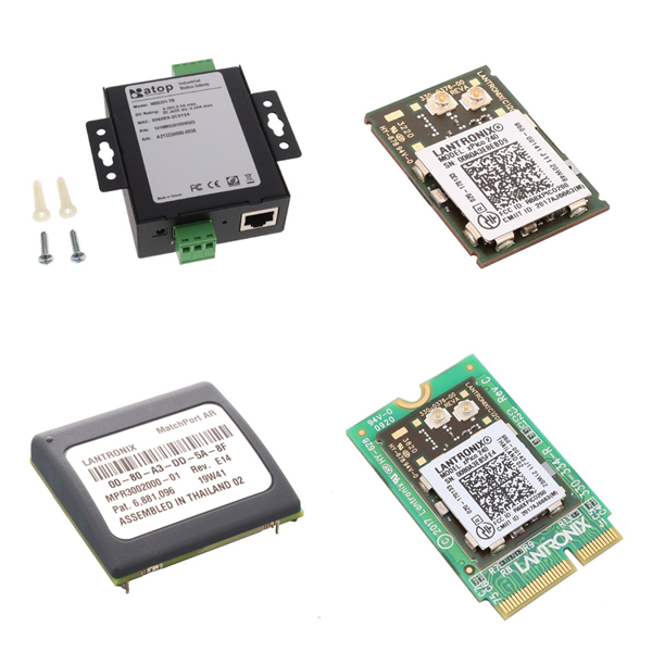
Networking Solutions The Network Solutions product category includes devices used to establish information connections between devices, data sources, and data sinks. Included products include switches, hubs, and routers used to establish connections between numerous devices that communicate using similar protocols, media converters used to connect devices that communicate over different media (such as fiber optics and twisted pair copper conductors), and servers used to connect devices that communicate using protocols of varying complexity (such as RS232/422/485 to Ethernet or USB).

Development Boards, Kits, Programmers 1 What are Development Boards, Kits and Programmers? Development boards and kits usually include microcontrollers, peripheral interfaces, and debugging modules, providing engineers with a platform to quickly verify designs, test algorithms or learn chip functions. Programmers are used to burn code to the target chip and support firmware updates and debugging. 2 What are the Main Product Types of Development Boards and Kits? <strong>Educational Kits</strong>: Such as the educational kits of the Arm University Program, which are designed for teaching scenarios to help students learn the Cortex-M series architecture and embedded development technology. <strong>Cloud Platform Integration Kits</strong>: For example, solutions provided by Enmo Technologies support uploading sensor data from STMicro SensorTile or TI SimpleLink™ SensorTag directly to the cloud. <strong>Wireless Communication Kits</strong>: Such as Nordic Semiconductor's nRF9160 system-in-package (SiP) kit, which integrates cellular IoT and low-power Bluetooth functions. <strong>Display Evaluation Kit</strong>: Such as the E-ink screen development kit of Pervasive Displays, which is used for prototyping of e-paper display modules. 3 Where are Development Boards and Kits Used for? <strong>Education and Training</strong>: The learning threshold is lowered through standardized hardware and supporting teaching materials, which is suitable for university laboratories and internal training of enterprises. <strong>Industrial Internet of Things (IIoT)</strong>: Supports sensor data acquisition, edge computing and remote monitoring functions, and is often used for rapid prototyping of smart devices. <strong>Embedded System Development</strong>: Provides debugging interfaces compatible with different chip architectures (such as ARM Cortex-M) to shorten product development cycles. 4 Typical Manufacturers for Development Boards and Kits <strong>ARM</strong>: Provides the Versatile Express series development board based on Cortex-M, which supports a variety of peripheral expansions. <strong>Renesas</strong>: The DK-S124 development board is designed for low-power embedded systems and is suitable for sensor networks and wearable devices. <strong>Nordic Semiconductor</strong>: With wireless communication as the core, it launches an integrated development kit that integrates radio frequency (RF) and microcontrollers.

Motors, Actuators, Solenoids and Drivers 1. Core Components Overview <strong>Motors</strong>: As the power source of mechanical systems, common types include DC motors and brushless motors. Portescap's 20DAM series digital linear actuators combine high linear force (up to 108 ounces) with low-cost design for precision control scenarios. <strong>Actuators</strong>: Responsible for converting electrical signals or energy into mechanical actions, they are widely used in industrial automation, aerospace and automotive fields. They include mechanical, electronic and electromagnetic types. <strong>Solenoids</strong>: A type of electromagnetic actuator that drives the core to move through the coil current. They are commonly used in valve control, switch devices, and automotive transmission systems. For example, Unick's transmission actuators include solenoid valves and valve assemblies for emission control systems. <strong>Drivers</strong>: Provide control signals and power output for motors and solenoids. Texas Instruments' (TI) motor driver solution solves the current fluctuation and efficiency problems in solenoid drive by optimizing the power architecture. 2. What are Motors, Actuators, Solenoids and Drivers Used for? <strong>Industrial Automation</strong>: The growing demand for high-density digital I/O modules drives controllers toward compact, low-heat designs to support the integration of more sensors and actuators. <strong>Automotive Systems</strong>: Solenoids and electromagnetic actuators are used for transmission control, fuel injection, etc. and need to withstand high temperatures and vibration environments. <strong>Medical Equipment</strong>: Portescap's motor technology is used in medical infusion systems, emphasizing high precision and reliability. 3. What are the Technology Trends and Challenges of Motors, Actuators, Solenoids and Drivers? <strong>Integrated Design</strong>: ADI Trinamic™ proposes an intelligent drive solution that improves actuator response speed and energy efficiency by integrating driver chips with edge computing capabilities. <strong>Drive Optimization</strong>: The inductance characteristics of the solenoid and the change in mechanical load require the driver to have dynamic current regulation capabilities. TI's solution reduces electromagnetic interference through adaptive algorithms. <strong>High-density Control</strong>: Industrial controllers need to process more digital I/O signals in a limited space, driving innovations in modular circuit design and heat dissipation technology. 4. What is the Industry Development Direction of Motors, Actuators, Solenoids and Drivers? <strong>Intelligent</strong>: Actuators and drivers gradually integrate real-time feedback and communication functions to support remote monitoring and predictive maintenance. <strong>Energy efficiency improvement</strong>: The popularization of brushless motors and low-power drivers helps industrial equipment reduce energy consumption. Motors, Actuators, Solenoids and Drivers FAQs 1. How do you choose a suitable motor driver? The following factors should be considered comprehensively: <strong>Motor Type</strong>: DC, stepper, or AC motors need to match the corresponding driver; <strong>Control Accuracy</strong>: For example, the stepper motor driver needs to support subdivision control; <strong>Power Requirement</strong>: Select according to the load current and voltage range; <strong>Integration Capability</strong>: Whether it supports the communication interface with the microcontroller or PLC. 2. What is the relationship between the driver and the motor device? The driver and the motor together constitute a complete drive system. The driver directly affects the performance of the device (such as energy consumption and quietness) by adjusting the power conversion efficiency, while the motor body determines the upper limit of the mechanical output. 3. How does the high-density digital IO module optimize the controller design? In industrial automation, high-density IO modules reduce the use of discrete components by integrating FET and signal conditioning circuits, thereby reducing the size and heat generation, and supporting digital signal processing with more channels. 4. What are the common faults of motor drivers? <strong>Overheating</strong>: caused by overload or poor heat dissipation; Abnormal Control Signal: such as pulse loss or unstable voltage; <strong>Interface Compatibility Issues</strong>: mismatch with the communication protocol of the microcontroller or sensor. 5. What are the common communication interfaces between the driver and the microcontroller? <strong>PWM Signal</strong>: control speed or position through pulse width modulation; <strong>UART/I2C</strong>: used for parameter configuration and status feedback; <strong>CAN Bus</strong>: suitable for industrial multi-node communication scenarios. 6. What are the possible causes and solutions for actuator response delay? <strong>Mechanical Jam</strong>: lubricate or replace worn parts; <strong>Drive Signal Delay</strong>: check the controller code logic or signal transmission path; <strong>Insufficient Power Supply</strong>: ensure that the supply voltage and current meet the load requirements.
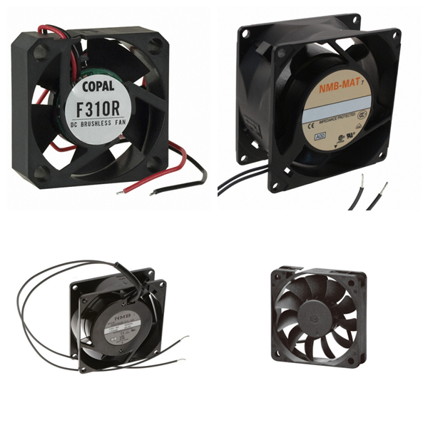
Fans, Blowers, Thermal Management 1.What are Fans, Blowers and Thermal Management? <strong>Fans and blowers</strong>: They are active heat dissipation devices that remove heat generated by components through forced air flow (thermal convection) to reduce local or system temperature. <strong>Thermal management</strong>: Comprehensive use of heat dissipation design, material selection, and cooling technology to ensure that the temperature of components is within the safe threshold and ensure the stability and life of the equipment. 2. What is the working principle of Fans, Blowers and Thermal Management? <strong>Active heat dissipation technology</strong>: <strong>√Fans</strong>: Drive airflow through blade rotation, commonly used in general electronic devices (such as computers and servers). <strong>√Blowers</strong>: Provide higher wind pressure and directional airflow, suitable for scenarios with limited space or centralized heat dissipation (such as avionics packaging). <strong>Heat transfer mechanism</strong>: Heat is dissipated through three paths: thermal conduction (heat sink, thermal pad), thermal convection (forced airflow), and thermal radiation (high emissivity material). 3. Where are Fans, Blowers and Thermal Management Used for? <strong>Consumer electronics</strong>: In mobile phones, computers, and other devices, fans are used to dissipate CPU/GPU heat and prevent performance throttling. <strong>High-power devices</strong>: such as high-power chips and LED modules, require blowers or liquid cooling systems to cope with high heat flux density. <strong>Harsh environments</strong>: In scenarios such as avionics, microblowers are preferred due to their low noise and low electromagnetic interference characteristics. 4. What are the Challenges of Fans, Blowers and Thermal Management? <strong>Efficiency improvement</strong>: The heat dissipation effect can be enhanced by increasing the heat dissipation area, optimizing the air duct design, or increasing the fan speed, but the noise and energy consumption need to be balanced. <strong>Reliability issues</strong>: Traditional fans may have a shortened life due to mechanical vibration and accumulation of pollutants, and need to be combined with a temperature control system to achieve dynamic adjustment. 5. What are the Development Trends of Fans, Blowers and Thermal Management? <strong>Miniaturization and integration</strong>: The combination of micro blowers, heat pipes, and other technologies meets the efficient heat dissipation needs of small devices. <strong>Intelligent temperature control</strong>: Combine temperature sensors with adaptive algorithms to achieve dynamic optimization of heat dissipation strategies.

Industrial Automation and Controls 1. What are the Core Components of Industrial Automation Products? 1)Controller <strong>PLC (Programmable Logic Controller)</strong>: As the "brain" of the industrial automation system, PLC implements logical operations, data processing and equipment communication through programming, replacing the traditional relay system, and has high reliability, flexibility and scalability. <strong>Intelligent controller</strong>: Supports complex algorithms and multi-device collaborative control, and is widely used in production lines, energy management and other scenarios. 2)Sensors and actuators <strong>Sensors</strong>: Including temperature, pressure, photoelectric and other types, used to monitor physical quantities in real time and convert them into electrical signals to provide data input for the system. <strong>Electric actuator</strong>: Drive mechanical movement through electric motors to achieve precise control of equipment such as valves and conveyor belts, support remote operation, and automated processes. 3)Auxiliary components <strong>Circuit breakers and relays</strong>: Ensure circuit safety, and achieve signal isolation and load control. <strong>Inverter and servo system</strong>: Used for motor speed regulation and precision motion control to improve production efficiency and energy consumption management. 2. Where are Industrial Automation Products Used for? <strong>Production line automation</strong>: Monitor parameters through sensors and adjust equipment status through PLC to ensure product quality and production efficiency. <strong>Energy and environmental management</strong>: Applied to pumping stations, sewage treatment, exhaust gas monitoring, and other systems to achieve remote control and energy-saving optimization. <strong>Intelligent manufacturing</strong>: Combined with machine vision (industrial cameras), 3D modeling, and other technologies, promote flexible manufacturing and smart factory construction. 3. What are the Technical Features of Industrial Automation Products? <strong>Programmability</strong>: Support flexible configuration of control logic to adapt to diverse industrial scenarios. <strong>High precision and reliability</strong>: Millimeter-level control is achieved through components such as encoders and gratings to ensure long-term stable operation of the system. <strong>System integration</strong>: Supports interconnection with MES, SCADA, and other systems to build a data-driven remote monitoring and management platform. 4. What are the Frontier Trends of Industrial Automation Products? <strong>Intelligent sensors</strong>: Integrate edge computing capabilities to achieve real-time data analysis and local decision-making. <strong>Modular design</strong>: Simplify equipment deployment and maintenance through standardized interfaces (such as communication modules). <strong>Green Automation</strong>: Optimize energy consumption algorithms and integrate renewable energy to promote sustainable development.

Battery Products 1.What are the Core Components of Battery Products? <strong>Cell</strong>: As the basic unit of the battery, it is composed of a positive electrode, a negative electrode, a separator and an electrolyte, providing a voltage output of 3V-4V. The materials include lithium-ion, nickel metal hydride or lead acid, etc. <strong>Batteries</strong>: It is composed of multiple cells connected in series/parallel to increase voltage or capacity, such as 12V modules or high-capacity combinations. <strong>Battery Pack</strong>: It is integrated by a battery pack and equipped with a battery management system (BMS) to form a product that can be directly applied, such as an electric vehicle lithium battery pack. 2. What are the Packaging Types of Battery Products? <strong>Hardshell packaging</strong>: It uses steel/aluminum materials and is divided into cylindrical (high production efficiency) and square (compact structure). <strong>Soft package packaging</strong>: It uses aluminum-plastic film, which has the advantages of lightweight and high energy density, but the degree of automation is low. <strong>Supercapacitor</strong>: It is between batteries and traditional capacitors, supports fast charging and discharging, and has a long cycle life, and is suitable for high-power scenarios. 3. What are the Technical Features of Battery Products? <strong>Patented technology</strong>: such as heating connector design, optimizing thermal management of battery box and external environment. <strong>Material innovatio</strong><strong>n</strong>: Graphene electrodes improve conductivity, and ionic liquid electrolytes enhance stability. <strong>Process differences</strong>: The cylindrical winding process is highly efficient, and the square stacking process is suitable for soft-pack batteries. 4. What are Battery Products Used for? <strong>Consumer electronics</strong>: mobile power supplies, smart devices, etc.. <strong>Industry and transportation</strong>: electric vehicle power batteries, energy storage systems and outdoor equipment (such as garden tools). <strong>Emerging fields</strong>: high-power demand scenarios such as grid regulation and robots. 5. The Industry standards and compliance requirements of Battery Products <strong>Safety certification</strong>: Cross-border e-commerce needs to provide IEC/EN62133 or UL2054/UL1642 certification and temperature test reports. <strong>MSDS file</strong>: Lithium batteries must include component data, hazardous materials classification and emergency disposal plans to ensure safe transportation and use. International Standards: Following the GHS standards, each country should issue SDS documents (such as EU REACH, China GB/T 16483). 6.The Challenges and Development Directions of Battery Products <strong>Energy density improvement</strong>: Supercapacitors need to break through the bottleneck of low energy density. <strong>Cost and consistency</strong>: Soft-pack batteries rely on imported aluminum-plastic films, and production consistency needs to be improved. <strong>Environmental protection needs</strong>: Promote the research and development of green technologies such as cobalt-free batteries and solid electrolytes. 7. Battery Products FAQs 1) Whether the Temperature Affects the Life of the Battery Products? Yes. High or low-temperature environments may affect battery performance. It is recommended to avoid charging or discharging at extreme temperatures. Some batteries have low/high-temperature protection functions: <strong>When charging</strong>: Charging stops automatically when the temperature is below 0°C or above 55°C. <strong>When discharging</strong>: Discharging stops when the temperature is below –10°C or above 55°C. 2) What are the Precautions When Charging with Battery Products? Using the original charger can optimize charging efficiency and extend battery life. When using a new battery for the first time, it is recommended to fully charge and discharge to activate battery performance (applicable to some models). 3) How to Maintain the Battery Products? Regularly cleaning the internal blockages of the device (such as vacuum cleaner filters) can improve battery efficiency. When storing the battery for a long time, keep the power at 30%-50% to slow down aging. 4) How to Troubleshoot Battery Products? If the battery is abnormally hot or cannot be charged, it is recommended to contact the official after-sales service for inspection. Some batteries support remote positioning function (such as mobile phone batteries), which is convenient for tracking when the device is lost.

Discrete Semiconductor Products Discrete semiconductor devices refer to a collection of semiconductor components with independent packages and single functions, which complement integrated circuits (ICs). 1. What are the Core Features of Discrete Semiconductor Products? <strong>Independent packaging</strong>: Each device is packaged separately and can be directly soldered on a circuit board. <strong>Single function</strong>: Focus on achieving specific functions (such as switching, amplification, rectification, etc.). <strong>High flexibility</strong>: Supports building customized circuits by combining discrete devices to adapt to designs with special needs. 2. What are the Common Types of Discrete Semiconductor Products? <strong>Diodes</strong>: Used for rectification, voltage regulation (such as Zener diodes), light emission (LED), etc. <strong>Transistors</strong>: <strong>√ Bipolar transistors (BJT)</strong>: Current amplification and switch control. <strong>√ Field effect transistors (MOSFET/IGBT)</strong>: High-frequency switching and power control (such as power supplies, motor drives). <strong>Thyristors</strong>: Used for high-power switches (such as dimmers and motor speed control). <strong>Power devices</strong>: such as power MOSFET, IGBT, etc., support high power density and efficient energy conversion. 3. Where are Discrete Semiconductor Products Used for? <strong>Automotive electronics</strong>: such as high-precision LDO series directly connected to the car battery, integrated output protection function. <strong>Power management</strong>: Extend battery life through boost regulators and energy-saving functions (such as nPM2100 PMIC). <strong>Industrial control</strong>: Including motor drive, power conversion, high current switching, and other fields. <strong>RF and signal processing</strong>: such as variable capacitance diodes (Varactor) for RF tuning circuits. 4. What are the Advantages of Discrete Semiconductor Products? <strong>High power density</strong>: Provide higher power output in a miniaturized size that is suitable for compact devices. <strong>Low loss and high efficiency</strong>: Reduce energy waste and improve energy utilization efficiency (such as boost regulator applications). <strong>Fast response</strong>: Achieve precise control to meet immediate needs (such as switch control in power conversion). <strong>Temperature Management</strong>: Optimize heat dissipation performance and improve system stability and reliability. 5. What are Some Examples of Discrete Devices? MOSFET Bipolar Transistor Transistor Array Transistor with Internal Resistor NSAD Series NNCD Series RD Series SCR TRIAC Trigger Device 6. Discrete Semiconductor Products FAQs 1) How to suppress power supply noise in discrete devices? In high-speed circuit design, the power supply end of discrete devices needs to adopt a parallel capacitor solution (such as a combination of 0.01μF and a smaller capacitor) to cover the high-frequency band noise suppression requirements; it is also recommended to add a large-capacity capacitor (such as 10μF) at the power supply entrance to improve the overall decoupling effect. 2) What is the output protection mechanism of discrete devices? <strong>Short-circuit protection</strong>: Only LVDS output supports short-circuit protection, and it is necessary to ensure that the short-circuit current does not exceed the data sheet limit; LVPECL and CMOS outputs may cause device damage if they are accidentally grounded. <strong>Level limitation</strong>: CMOS output is usually limited to 3.3V LVCMOS level, and direct connection to a 5V system is prohibited to avoid over-voltage risk. 3) How can discrete devices be synchronized in a multi-chip system? Multi-chip synchronization requires strict matching of clock signal paths (such as equal-length wiring) and phase alignment through dedicated synchronization pins. For example, ADI clock chips support multi-device synchronization, but they need to be combined with external VCO/VCXO and loop filters to optimize clock stability. 4) How can discrete devices be more reliable in high-temperature environments? <strong>Material selection</strong>: Wide bandgap devices (such as SiC and GaN) can work stably in high-temperature environments above 200℃, which is better than traditional silicon-based devices. <strong>Heat dissipation optimization</strong>: It is necessary to use high thermal conductivity packaging (such as copper substrate) or an additional heat sink to reduce junction temperature to extend device life. 5) What are the configuration requirements for discrete devices to drive different loads? <strong>Power supply voltage adaptation</strong>: Some devices (such as AD9516) support separate power supply for LVPECL output, and the power supply voltage range needs to be adjusted according to load requirements. <strong>Drive capability matching</strong>: It is necessary to ensure that the output current is compatible with the load impedance, and the drive capability is enhanced by a buffer if necessary. 6) How to achieve better interface compatibility between discrete devices and digital systems? <strong>Level conversion</strong>: If the output level of the discrete device does not match the digital system (such as CMOS 3.3V→5V), a level conversion chip or voltage divider circuit needs to be added. <strong>Signal Isolation</strong>: In noise-sensitive scenarios, it is recommended to use optocouplers or magnetic isolation devices to block ground loop interference.

Isolators Isolators are key components used to achieve electrical isolation in electronic circuits. Their main function is to block direct electrical connections between different circuits while allowing unidirectional transmission of signals or energy, thereby improving the safety and anti-interference ability of the system. The following is a detailed description of its core features and application scenarios: 1. Isolators Overview 1)Basic composition Usually composed of optical couplers or transformers, and some high-frequency scenarios use RF-specific structures. There are various packaging forms, such as direct plug-in type, surface mount type (SMD), etc. Some high-end models use hermetic packaging to enhance weather resistance. 2)Core functions <strong>Electrical isolation</strong>: Isolate high-voltage and low-voltage circuits to prevent abnormal current flow from causing damage to equipment or personnel. <strong>Signal transmission</strong>: Realize cross-isolation transmission of signals through electromagnetic induction or photoelectric conversion to avoid ground loop interference. <strong>Decoupling and filtering</strong>: Separate DC components and AC noise in the power supply circuit to improve system stability. 2. What are Isolators Used for? <strong>Power supply and industrial system</strong> Decoupling circuit for power module to suppress high-frequency noise interference. Isolate control circuits and execution circuits in industrial automation equipment to prevent high-voltage shock from damaging sensitive components. <strong>Communication and RF field</strong> RF isolators (such as MACOM MADL series) are used in high-frequency systems such as wireless communication and radar, supporting 1 GHz to 2 GHz frequency bands, with an impedance of 50Ω to ensure the stability of signal transmission. Protect the front-end circuit of the receiver to avoid equipment damage caused by signal reflection. <strong>Medical and precision equipment</strong> Isolate the patient side from the main control circuit in medical equipment to ensure safety and compliance. Block common-mode interference in precision measuring instruments to improve signal acquisition accuracy. 3. How to Choose Isolators? 1)Key parameters <strong>Frequency range</strong>: For example, the RF isolator needs to match the system operating frequency band (such as 1.3 GHz). Insertion loss: Typical value is as low as 0.35 dB, reducing signal attenuation. <strong>Temperature resistance</strong>: The operating temperature range is usually -65°C to 125°C. 2)Classification and selection recommendations <strong>Photoelectric coupling type</strong>: Suitable for low-frequency signal isolation, and low cost. <strong>Transformer coupling type</strong>: Supports high frequency and energy transmission, but has a larger volume. <strong>RF dedicated type</strong>: Optimized for high-frequency scenarios, attention should be paid to impedance matching and packaging form. 4. Typical Brands for Isolators Infineon TOSHIBA Onsemi TI VISHAY LITEON 5. Isolators FAQs 1) How do Isolators work? <strong>Photocoupler</strong>: The input LED emits light, and the photosensitive element (such as a phototransistor) receives the light signal and converts it into an electrical signal, realizing no direct electrical connection between the input and the output. <strong>Capacitive Isolator</strong>: Through high-frequency signal modulation, energy or data is transferred using the capacitor medium, blocking DC and low-frequency interference. <strong>Inductive Isolator</strong>: Energy or signal is transferred using magnetic field coupling, isolating the primary and secondary circuits. 2) What are the common failure mechanisms of Isolators and how to avoid them? <strong>Optical Attenuation of Optocouplers</strong>: LED aging causes signal transmission failure, so it is necessary to select high-reliability models and avoid long-term overload. <strong>Capacitive Isolation Breakdown</strong>: Overvoltage or dielectric aging causes short circuits, so it is necessary to strictly limit the operating voltage and add protection circuits. <strong>Inductive Isolation Saturation</strong>: The magnetic field is too strong, resulting in a decrease in efficiency, and the core material and drive current need to be optimized. 3) How to determine whether the isolation level of Isolators meets the requirements? The isolation level needs to be comprehensively evaluated based on the system's maximum operating voltage, transient overvoltage (such as lightning strikes or switching surges), and safety standards (such as IEC 61010). For example, medical equipment usually requires reinforced isolation (such as 5000Vrms), while industrial control scenarios may only require basic isolation (2500Vrms). 4) What factors affect the life of isolators? <strong>Optocoupler</strong>: LED light decay is the main factor. Long-term high temperature or overcurrent will accelerate aging. It is recommended to control the forward current within 60% of the rated value. <strong>Capacitive Isolator</strong>: The aging of the dielectric material or moisture penetration may cause capacitance drift. Moisture-resistant packaging (such as ceramic dielectric) is required. <strong>Solid-State Relay</strong>: The number of switching times and load type (capacitive/inductive) affect the contact life. The life under resistive load can reach more than 10^7 times. 5) What are the common design issues of isolators in I2C communication? <strong>Bidirectional Signal Conflict</strong>: Direct use of unidirectional isolators will cause bus latch failure. It is necessary to select a dedicated isolation I2C chip (such as ISO1540) or implement bidirectional isolation through an external logic circuit. <strong>Signal Delay</strong>: The transmission delay of the isolation device must be less than the minimum clock cycle of the I2C bus. For example, a 100kHz bus requires a delay of ≤ 1μs. <strong>Power Consumption Matching</strong>: The pull-up resistor values on both sides of the isolator must match the bus driving capability to avoid abnormal logic levels due to impedance mismatch. 6) What is the difference between isolators and other protection devices (such as TVS diodes)? <strong>Functional Difference</strong>: Isolators achieve electrical isolation and block common-mode interference and ground loops; TVS diodes are mainly used to suppress transient overvoltages (such as ESD) and belong to clamping protection. <strong>Application Scenarios</strong>: Isolators are suitable for long-term isolation needs (such as power systems), while TVS diodes are used for short-term pulse protection (such as communication ports). <strong>Cooperative Use</strong>: In a high-voltage environment, isolators and TVS diodes can be connected in series, the former isolating continuous interference, and the latter absorbing transient energy. 7) How to test the isolation performance of isolators? <strong>Withstand Voltage Test</strong>: Use a withstand voltage tester to apply isolation voltage (such as 3000Vrms/1 minute) to detect whether the leakage current exceeds the standard (usually ≤ 1mA). <strong>Transmission Characteristics Test</strong>: Input a square wave through a signal generator, and observe the waveform distortion and delay at the output end with an oscilloscope to verify whether the bandwidth meets the standard. <strong>Temperature Rise Test</strong>: Continuously operate at the highest operating temperature to monitor whether the isolation medium has a breakdown or parameter drift. 6. Summary Isolators ensure circuit safety and signal integrity through physical isolation and are indispensable components in power supply, communication, industry, and medical fields. When selecting, it is necessary to consider the frequency requirements, isolation strength, and packaging form.

Power Supplies - Board Mount 1. Overview 1)Basic Concepts “Power Supplies - Board Mount” refers to compact power modules that can be directly mounted on a printed circuit board (PCB), including AC/DC or DC/DC conversion functions, and are used to provide stable power for electronic devices. 2)Main Types <strong>Isolated Modules</strong>: The input and output ends are electrically isolated by a transformer, and the isolation voltage is usually 1.5kV-3kV, which is suitable for scenarios with high anti-interference requirements. <strong>Non-isolated Modules</strong>: Smaller and lower in cost, suitable for applications with limited space and no isolation. 2. What are the Core Parameters and Features of Board Mounted Power? 1)Input/Output Range <strong>Input Voltage</strong>: Covers a wide range of inputs, such as DC 0.7V-15V (low voltage scenario) or AC 90V-264V (universal AC input). <strong>Output Voltage</strong>: Supports single or multiple outputs, such as DC 1.8V, 5V, 12V, 500V, etc., to meet different load requirements. 2)Power and Efficiency The power range is from 4W (AC/DC module) to 120W (high-voltage DC/DC module), and the efficiency is generally higher than 85%, and some models can reach 88.5%. Adopt interleaved PFC (power factor correction) and PSFB (phase-shifted full-bridge) topology to improve energy efficiency. 3)Safety and Certification Complies with EN55022 Class B electromagnetic compatibility standard passes 3kV isolation voltage test and has overcurrent (OCP), overvoltage (OVP), and over temperature (OTP) protection functions. 3. What is Board Mounted Power Used for? <strong>Industrial control equipment</strong>: such as PLC and sensor power supply, which need to withstand wide temperature environment (-40 °C to 100 °C) and vibration conditions. <strong>Communication infrastructure</strong>: CRPS (common redundant power supply) architecture is used in servers and switches to support hot plugging and redundant backup. <strong>Medical and test instruments</strong>: Modules that rely on high isolation voltage and low noise output to ensure equipment safety and accuracy. 4. How to Choose Board Mounted Power? <strong>Load matching</strong>: Select a model with a power margin of ≥20% based on the device power consumption to avoid overload. <strong>Installation method</strong>: Give priority to standard packaging (such as 1/8 Brick size) and compatible with PCB layout requirements. <strong>Management interface</strong>: Some modules support PMBus/SMBus protocols to facilitate remote monitoring of power status. 5. Board Mounted Power FAQs 1) Which components are prone to power failure? <strong>Electrolytic Capacitors</strong>: Common failures include reduced capacity, leakage, or short circuits, which may cause unstable power output or complete failure. <strong>Resistors</strong>: Low-resistance resistors are easily burned due to overcurrent, and high-resistance resistors may drift due to aging, affecting the voltage division or current limiting function of the power supply. <strong>SMT Components</strong>: SMT components are small, and poor welding or thermal stress may cause contact failure. 2) How to detect power supply-related component failures? <strong>Capacitor Test</strong>: Use a multimeter to measure whether the capacity has decreased, or observe whether there is physical damage such as bulging or leakage. <strong>Resistance Test</strong>: Low-resistance resistors are easy to identify when they are burnt and blackened, and high-resistance resistors need to measure whether the resistance is abnormal. <strong>Short Circuit Troubleshooting</strong>: Use the adjustable power supply to gradually increase the pressure and observe the heating element to locate the short circuit point. 3) What are the possible reasons for the abnormal output of the power module? <strong>Capacitor Failure</strong>: The decrease in the capacity of the filter capacitor will cause the output voltage ripple to increase. <strong>Welding Problem</strong>: Cold welding or cold welding may cause poor contact, which may be good or bad. <strong>External Interference</strong>: Unshielded power lines may introduce noise, so grounding and shielding measures need to be checked. 4) How to test the stability of power supply output? <strong>Ripple Test</strong>: Use an oscilloscope to measure the AC component of the output voltage, which must meet the design specifications (such as <50mV). <strong>Load Regulation</strong>: Test the voltage fluctuation range under different loads. <strong>Transient Response</strong>: Observe the recovery time and overshoot voltage through step load changes.

Memory - Modules, Cards Memory - Modules, Cards mainly refer to integrated memory modules and memory card products, whose core function is to provide high-performance, high-density data storage solutions for various electronic devices. 1. Overview <strong>Memory Modules</strong> Usually, multiple memory chips (such as DRAM or SRAM) are integrated on a PCB substrate and connected to the main system through a standardized interface. For example, memory sticks (DIMM/SO-DIMM) belong to this category. Multiple DRAM chips form a super-cell array inside, and data addressing is achieved through row and column addresses (RAS/CAS). <strong>Memory Cards</strong> Including portable storage media such as CompactFlash and SD cards, using flash memory technology (such as NAND Flash) to achieve non-volatile data storage, suitable for mobile devices or embedded systems. 2. What the Main Types of Memory Modules and Cards? <strong>Dynamic Random Access Modules (DRAM Modules)</strong> Such as DDR4/DDR5 memory sticks, which increase the data transmission rate through synchronous clocks and are widely used in computer main memory. <strong>Static Random Access Modules (SRAM Modules)</strong> Applicable to high-speed cache scenarios, due to the low latency characteristics of the bistable circuit design, but the cost is relatively high. <strong>Specialized Memory Cards</strong> Such as the industrial-grade OMG-COMM8-PCI card, which supports specific protocols (such as CompactPCI) and is used in communication equipment or industrial control systems. 3. Brands and Manufacturers for Memory Modules and Cards <strong>Mainstream brands</strong> Kingston, Samsung, Micron, etc. provide standardized memory modules; Dataram, Meritec, and other manufacturers focus on customized storage solutions. <strong>Technical Features</strong> High-end modules use heat sink packaging (such as FBD-533 memory) and support ECC verification to improve data reliability. 4. What are Memory Modules and Cards Used for? <strong>Servers and Data Centers</strong> Large-capacity RDIMM/LRDIMM modules are used to increase server memory bandwidth and capacity. <strong>Embedded Systems</strong> Memory cards such as CompactFlash are suitable for IoT devices and industrial controllers due to their small size and low power consumption. <strong>Consumer Electronics</strong> DDR memory sticks and SD cards are widely used in terminal devices such as PCs and smartphones. The technological evolution direction of such products is higher density (such as 3D stacking technology), lower power consumption (LPDDR5), and higher speed interface (PCIe 5.0). <strong>Memory Modules and Cards FAQs</strong> 1. How do you choose memory modules and cards? <strong>Capacity</strong>: Choose according to the device requirements, for example, 4K/8K video shooting requires 128 GB and above. <strong>Speed level</strong>: Pay attention to the write speed (such as V30, V60) to ensure smooth HD video recording. <strong>Compatibility</strong>: Confirm the card types (such as SDXC and microSDXC) and maximum capacity limits supported by the device. 2. What is the Relationship between memory cards and passive components? The memory card is composed of NAND flash memory chips (passive components) and control circuits (active components) and is a hybrid electronic component. The core storage unit relies on semiconductor technology and meets the basic characteristics of integrated circuits (ICs). 3. How to maintain memory modules and cards? <strong>Formatting</strong>: Format in the device before first use to avoid compatibility issues. <strong>Data backup</strong>: Export content regularly to prevent data loss due to physical damage. <strong>Avoid extreme environments</strong>: High temperature, humidity or magnetic fields may affect the life of the memory card.
Sensors, Transducers 1. Overview <strong>Sensors</strong> A detection device that can sense the measured information and convert it into electrical signals or other usable forms according to specific rules to meet the needs of information transmission, processing, storage, and control. Its core consists of sensitive elements (sense the measured quantity) and conversion elements (converted into electrical parameters). <strong>Transducers</strong> Broadly speaking, it refers to a device that converts energy or signals from one form to another. In the field of electronics, it often refers to a device that converts non-electrical quantities (such as temperature and pressure) into electrical signals, which partially overlap with the functions of sensors. 2. What are the Core Characteristics and Classification of Sensors and Transducers? 1)Technical Features <strong>Sensors</strong>: miniaturized, digital, intelligent, and with high sensitivity and resolution. <strong>Transducers</strong>: emphasize the conversion efficiency and accuracy of the signal form, such as converting mechanical vibration into a voltage signal. 2)Classification Method <strong>By energy form</strong>: physical type (such as light, heat), chemical type (such as gas), biological type (such as enzyme sensor) <strong>By technical principle</strong>: resistive, capacitive, piezoelectric, etc. <strong>By application scenario</strong>: industrial control, environmental monitoring, medical equipment, etc. 3. Technology development and typical applications of Sensors and Transducers 1)Technology evolution In the early days, structural sensors were the main type (such as resistance strain gauges); Solid-state sensors emerged after the 1970s and semiconductor materials were used to improve performance; MEMS (micro-electromechanical system) technology promoted the miniaturization and integration of sensors, such as the acceleration sensor of automobile airbags. 2)Typical application scenarios <strong>Industrial automation</strong>: pressure sensors are used for process control, and photoelectric sensors realize object detection. <strong>Consumer electronics</strong>: gyroscopes (MEMS) and temperature and humidity sensors in smartphones. <strong>Internet of Things (IoT)</strong>: Environmental monitoring nodes rely on a variety of sensors and wireless transmission converters. 4. What are the Industry Trends of Sensors and Transducers? <strong>Intelligent integration</strong>: sensors combined with AI to achieve edge computing and adaptive calibration. <strong>Application of new materials</strong>: such as aluminum nitride sensors can work stably in high-temperature (900 °C) environments. <strong>Interdisciplinary integration</strong>: MEMS technology combines microelectronics and mechanical processing to give rise to new sensing systems. 5. Typical Brands for Sensors and Transducers Omron VISHAY TI SICK BOURNS YAGEO Onsemi Molex ALLEGRO 6. Sensors FAQs 1) How to calibrate the output signal of the sensor? Calibration needs to be based on the standard reference value of the physical quantity and is achieved by adjusting the measuring resistance (RM/RB) or configuring the gain parameters of the ASIC chip to ensure that the output signal corresponds linearly to the input quantity. 2) What environmental interference should be paid attention to when installing the sensor? Strong magnetic fields and high-frequency noise sources (such as motors and inverters) should be avoided, and mechanical vibration and temperature fluctuations should be ensured to be within the allowable range of the sensor. 3) How to deal with the zero drift problem of the sensor? Zero drift may be caused by temperature changes or long-term use. Noise can be suppressed by regular calibration, selecting temperature-compensated sensors, or adding filtering circuits. 4) Does the sensor output signal need to be amplified? How to choose an amplifier? When the sensor output signal is weak (such as mV level), it needs to be matched with a high-precision operational amplifier (Op-Amp). When selecting, attention should be paid to bandwidth, noise figure, and common mode rejection ratio (CMRR). 5) How to convert analog sensor signals into digital signals? An analog-to-digital converter (ADC) can be used, and the resolution must match the sensor accuracy (such as 12-bit or 16-bit ADC), and communicate with the microcontroller through the SPI/I²C interface. 6) How to ensure sensor safety in high voltage environment? Select sensors with insulation that withstand voltage levels that meet the requirements (such as isolated Hall sensors), and design sufficient creepage distance and electrical clearance. 7) How to ensure the performance of sensors under extreme temperatures? Select wide temperature sensors (such as -40°C to 125°C), and avoid the core material from decreasing magnetic permeability due to temperature changes. 8) How to determine whether the sensor is damaged? <strong>Detection methods include</strong>: measuring whether the power supply voltage is normal, whether the output signal is within the theoretical range, and observing whether the linearity is abnormal. 9) What should I do if the performance of the sensor deteriorates after long-term non-use? It may be caused by material aging or residual magnetism of the core, and a recalibration or demagnetization operation is required to restore the core to its original state. 10) How to choose pressure sensors in industrial automation? The selection should be based on the medium type (liquid/gas), pressure range (such as 0-10MPa), and output type (analog/digital). Stainless steel housing and corrosion-resistant design are preferred. 11) What sensors are commonly used in smart homes? Including temperature and humidity sensors (such as NTC thermistors), human infrared sensors (PIR), and air quality sensors (such as PM2.5 detection modules).

RF and Wireless 1. Radio Frequency (RF) Overview <strong>1) Definition and Frequency Band</strong>: Radio Frequency refers to electromagnetic waves in the 300kHz-300GHz frequency band, which has high-frequency alternating characteristics and is the basic carrier of wireless signal transmission. <strong>2) Key Components</strong>: <strong>Passive devices</strong>: including inductors, capacitors, directional couplers and waveguides, etc., are used for signal matching, filtering, and power distribution. <strong>Active devices</strong>: such as microwave power amplifiers, diodes, and transistors, which undertake signal amplification, modulation, and demodulation functions. <strong>Connector</strong>: RF connectors (such as SMA and BNC) are used as electrical interfaces of transmission lines to ensure low-loss transmission of high-frequency signals. 2. What is the Classification of Wireless Communication Technologies? 1)Short-Range Communication <strong>Bluetooth</strong>: Based on the IEEE 802.15.1 standard, it uses the 2.4GHz ISM frequency band and a master-slave structure, which is suitable for low-power device interconnection. <strong>Wi-F</strong><strong>i</strong>: Follows IEEE 802.11 protocol, supports 2.4GHz/5GHz frequency bands, provides high-speed LAN access, and requires optimization of microstrip or coplanar waveguide transmission line impedance during design. <strong>RF</strong>: Such as 315MHz/433MHz frequency bands, used for remote controls and access control systems, with low transmission rates but low costs and complexity. 2)Wide Area Communications <strong>Mobile Network (4G/5G)</strong>: Integrates cellular technology and WLAN to achieve high-bandwidth, low-latency data transmission. <strong>LPWAN technology</strong>: Such as NB-IoT, designed specifically for the Internet of Things, covering long-distance, low-power scenarios. 3. What is RF and Wireless Used for? <strong>RF Module</strong>: Integrates high-frequency transceiver circuits, supports 1M-2Mbps rates, and is used in vehicle monitoring, industrial data collection, and smart homes. <strong>Antenna design</strong>: It is necessary to consider PCB stacking (such as L2 as RF reference ground in the four-layer board), routing continuity to avoid signal reflection, and matching network optimization (such as parallel capacitors and series inductors) to improve efficiency. 4. How to Evaluate RF and Wireless? <strong>Performance indicators</strong>: Including transmission power, frequency error, adjacent channel leakage ratio (ACLR) and receiving sensitivity, etc., which need to be tested by conduction and radiation methods. <strong>International certification</strong>: Such as FCC (USA), CE (EU), and TELEC (Japan), to ensure that the equipment complies with electromagnetic compatibility and RF specifications. 5. What is the Development Trend of RF and Wireless? <strong>High frequency</strong>: Expand to millimeter wave (30-300GHz) to meet 5G/6G requirements. <strong>Integration</strong>: SOC (system on chip) integrates RF front-end and baseband processing to reduce power consumption and volume.
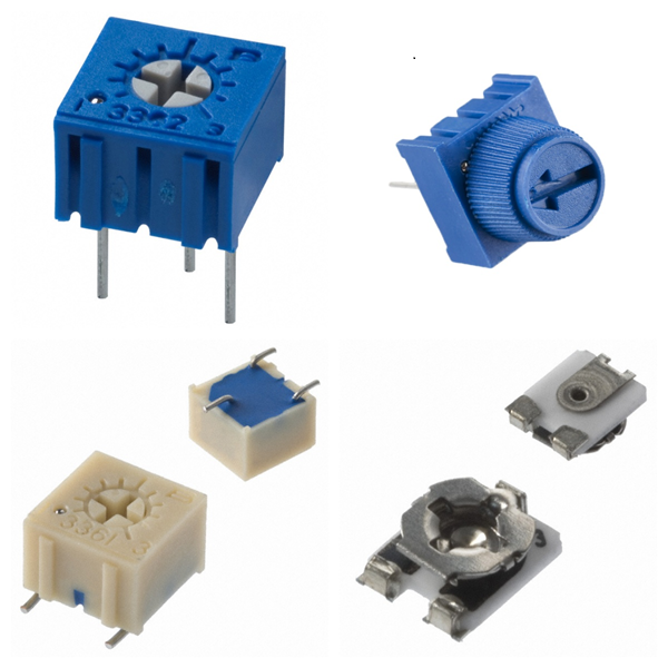
Potentiometers, Variable Resistors 1. Potentiometers and Variable Resistors Overview <strong>Potentiometer</strong>: A resistor element with three terminals and adjustable resistance. The resistance value is changed by sliding contacts to achieve voltage division or current limiting functions. Its core principle is to change the length of the current path or the contact area by adjusting the contact position, thereby changing the output resistance. <strong>Variable Resistors</strong>: In a broad sense, it includes potentiometers, but in a narrow sense, it refers to variable resistors with only two effective terminals (such as fine-tuning resistors). The resistance value is changed by adjusting the mechanical structure, and it is often used for circuit calibration or debugging. 2. What is the Structure and Working Principle of Potentiometers? <strong>Structure</strong>: The potentiometer consists of a resistor element (such as carbon film, and wire-wound resistor) and a sliding contact. The two ends of the resistor element are fixed terminals, and the sliding end (brush) changes the contact point position by rotation or linear movement. <strong>Voltage division principle</strong>: The input voltage is applied to the two ends of the resistor element, and the voltage output between the sliding end and any fixed end is proportional to the contact position, realizing the voltage division function. 3. What are the Common Types of Potentiometers? 1)By adjustment method: <strong>Rotary potentiometer</strong>: Adjusted by knob, widely used in volume control, brightness adjustment, etc. <strong>Linear (sliding) potentiometer</strong>: Adjusted by linear sliding, suitable for scenarios requiring linear response (such as dimmers). <strong>Trimmer</strong>: Miniaturized design requires tool adjustment and is used for circuit debugging or calibration. 2)By material and power: <strong>Carbon film/ceramic film potentiometer</strong>: Low cost, suitable for low power scenarios. <strong>Wire wound potentiometer</strong>: High power, high precision, used for industrial control. 4. What are Potentiometers Used for? <strong>Voltage division and signal adjustment</strong>: Audio equipment volume control, sensor signal adjustment. <strong>Power control</strong>: Light dimmer, motor speed adjustment (pay attention to power limit). <strong>Calibration and debugging</strong>: Trimmer resistors are used for precise adjustment of circuit parameters (such as bias voltage). 5. What are the Key Parameters of Potentiometers? <strong>Resistance range</strong>: Commonly from a few hundred ohms to megohms, selected according to the application. <strong>Power rating</strong>: Determines the maximum power consumption that can be tolerated (such as 0.1W to 5W). <strong>Linearity</strong>: The corresponding relationship between the change in resistance and the movement of the contact, affects the control accuracy. <strong>Mechanical life</strong>: The number of rotations or slides (usually tens of thousands of times). 6. What is the Special Function Design of Potentiometers? <strong>Attached switch</strong>: Some potentiometers integrate power switches, which are common in volume control knobs (triggered off when the contact is adjusted to the minimum resistance value). <strong>Multi-gang potentiometer</strong>: Multiple resistance units are linked, used in stereo audio equipment. 7. Typical Brands for Potentiometers BOURNS VISHAY TE ALPHA Panasonic Amphenol 8. Potentiometers FAQs 1) What is the difference between a potentiometer and a variable resistor? <strong>Potentiometer</strong>: Usually used as a three-terminal component, it outputs a voltage proportional to the contact position through the voltage division principle. <strong>Variable Resistor</strong>: Generally used as a two-terminal component, it only limits the current by adjusting the resistance value and has no voltage division function. 2) What are the advantages of digital potentiometers? It can be adjusted by a microprocessor or digital signal to support automatic control. Some models integrate non-volatile memory to retain the settings after power failure. It is small and high in precision, suitable for highly integrated circuits. 3) What are the common faults and detection methods of potentiometers? <strong>Poor Contact</strong>: It is manifested as a jump in the output signal. A multimeter can be used to detect whether the resistance value changes continuously. <strong>Mechanical Wear</strong>: Noise occurs when rotating or sliding, and the potentiometer needs to be replaced. <strong>Detection Steps</strong>: Measure whether the total resistance of the two ends meets the nominal value, and check whether the resistance between the sliding end and the fixed end changes linearly with the adjustment. 4) Which special potentiometers have additional functions? <strong>Potentiometer with switch</strong>: The switch can be triggered when rotating or sliding to the extreme position, which is often used in the integrated design of power switches and volume adjustment (such as old radios). <strong>Multi-gang potentiometer</strong>: Multiple potentiometers share the same adjustment axis, which is used to synchronously control multiple signals (such as stereo audio balance adjustment). 5) What role does the potentiometer play in analog-to-digital conversion? In the analog signal acquisition system, the potentiometer can be used as a voltage divider to provide a reference voltage and cooperate with the analog-to-digital converter (ADC) to convert analog signals (such as position and brightness) into digital signals. Summary Potentiometers and variable resistors adjust resistance values mechanically or digitally. They are core components of analog circuit control and are widely used in consumer electronics, industrial equipment, and debugging scenarios. Their selection needs to comprehensively consider resistance range, power, accuracy, and usage environment.

Crystals, Oscillators, Resonators Crystals, oscillators and resonators each have their own characteristics and different application scenarios. In actual design, frequency stability, power consumption, cost and environmental factors need to be considered comprehensively. 1. What are Crystals? <strong>Definition</strong>: Crystals are typical passive devices (Passive Device), the main component of which is quartz (SiO₂), which use the piezoelectric effect to realize the mutual conversion of mechanical vibration and electrical signals. <strong>Working principle</strong>: When an external voltage is applied, the crystal generates a resonant signal of a fixed frequency through mechanical vibration, but it does not have the driving ability itself and needs to rely on external circuits (such as amplifiers and load capacitors) to maintain oscillation. <strong>Application scenario</strong>: Commonly used in clock circuits (such as microcontrollers and communication equipment) to provide reference frequency, and the nominal frequency range covers kHz to MHz (such as 32.768kHz or 24MHz). 2. What are Oscillators? <strong>Definition</strong>: Oscillators are active devices (Active Device), which integrate internal amplifier circuits, feedback resistors and voltage stabilization components, and can independently generate stable frequency signals. <strong>Core features</strong>: √Directly output clock signals (such as sine waves or square waves) without external driving circuits. √Pins usually include power supply (VCC), ground (GND), output (OUT), etc., and the operating voltage supports 1.8V to 5V. √High frequency stability, less affected by temperature and voltage fluctuations, suitable for high-precision scenarios (such as communication base stations, satellite navigation). <strong>Classification</strong>: Including quartz crystal oscillators (XO), temperature-compensated oscillators (TCXO), voltage-controlled oscillators (VCXO), etc.. 3. What are Resonators? <strong>Definition</strong>: Resonators broadly include crystal resonators (Crystal Resonators) and ceramic resonators (Ceramic Resonators), both of which are passive devices and require external circuit excitation to work. <strong>Difference from crystals</strong>: √Structure: Crystal resonators are composed of a single quartz plate; ceramic resonators use piezoelectric ceramic materials, which are lower in cost but lower in precision. <strong>√Performance</strong>: Crystal resonators have higher frequency stability and lower aging rates; ceramic resonators are suitable for cost-sensitive medium and low-frequency scenarios (such as home appliance control). 4. Comparison of Crystals, Oscillators and Resonators Features Crystals Oscillators Resonators Device Type Passive Active Passive Drive Requirements External Circuit Required No External Circuit Required External Circuit Required Output Signal Resonant Signal (Amplification Required) Direct Output of Stable Clock Signal Resonant Signal (Amplification Required) Typical Applications High-precision clock reference Clock source for complex systems Low-cost, medium and low-frequency circuits Cost Medium High Low 5. How to Choose Crystals, Oscillators and Resonators? <strong>Accuracy First</strong>: Select a crystal or oscillator (such as TCXO) and optimize the circuit with load capacitance. <strong>Cost Sensitive</strong>: Ceramic resonators can replace low-frequency crystals, but pay attention to the problem of temperature frequency deviation. <strong>Power Consumption Limit</strong>: Silicon oscillators (such as MAX7375) are better than traditional discrete solutions in low-power scenarios.

Capacitors Capacitors play a vital role in electronic circuits. Reasonable selection and use are the keys to ensuring circuit performance. 1. Capacitors Overview A capacitor is a passive electronic component consisting of two conductors (plates) close to each other and a non-conductive insulating medium (dielectric) in the middle, used to store charge and electrical energy. Its core function is to achieve temporary storage and release of energy through the charging and discharging process. The calculation formula of capacitance (unit: Farad, F) is: C=εS/4πkd Where ε is the dielectric constant, S is the plate area, and d is the plate spacing. 2. What are the Core parameters of Capacitors? <strong>Capacitance</strong>: There is a tolerance between the nominal value and the actual value, and the accuracy is usually 5%~25%. <strong>Rated voltage</strong>: The maximum voltage limit for the normal operation of the capacitor. <strong>Dissipation factor</strong>: Reflects the energy loss of the dielectric material and the equivalent series resistance (ESR). <strong>Temperature coefficient</strong>: The effect of temperature change on capacitance, expressed in ppm (parts per million). <strong>Leakage current</strong>: Determined by dielectric insulation performance, affecting long-term stability. 3. What are the Types of Capacitors? 1)Differentiation by polarity: <strong>Non-polar capacitors</strong>: Such as ceramic capacitors and film capacitors, which can be installed in any direction, but have a small capacity. <strong>Polar capacitors</strong>: Such as electrolytic capacitors (aluminum electrolytic, tantalum capacitors), which have large capacity but must strictly distinguish between positive and negative poles. 2)Differentiation by structure: <strong>Fixed capacitors</strong>: The capacitance is immutable. <strong>Variable capacitors</strong>: Change the plate spacing or area through mechanical adjustment. 4.What are the Functions and Applications of Capacitors in Circuits? <strong>Power supply filtering</strong>: Smooth voltage fluctuations and suppress high-frequency noise. <strong>Signal coupling/decoupling</strong>: Block DC components and transmit AC signals. <strong>Energy storage and tuning</strong>: Used in resonant circuits, energy buffering and other scenarios. <strong>Timing control</strong>: Cooperate with resistors to realize RC charging and discharging delay function. 5. The Selection and Use Precautions of Capacitors <strong>1)Voltage margin</strong>: The rated voltage must be higher than the maximum operating voltage of the circuit. <strong>2)Temperature adaptability</strong>: A model with a stable temperature coefficient must be selected in a high-temperature environment. <strong>3)Polarity judgment</strong>: The short pin or the shell mark "-" is the negative pole of the electrolytic capacitor.The dark end of the tantalum capacitor is the negative pole. <strong>4) Installation form</strong>: The direct plug-in type is suitable for manual welding, and the SMD type is suitable for high-density PCB layout. 6. Which Brands Have the Best Capacitors? CHEMICON NICHICON YAGEO TDK AISHI 7. Capacitors FAQs (1) How to Use Tantalum Capacitors Safely? Avoid overvoltage or reverse voltage, otherwise, it may cause overheating or even short circuit; Some models support short-term over-temperature applications, but the derating guidelines provided by the manufacturer must be followed. (2) How to Choose Capacitors in Circuit Design? Low ESR capacitors (such as conductive polymer capacitors) should be preferred in power supply filtering scenarios to improve efficiency; High-frequency circuits need to consider the impact of ESL, and it is recommended to use multi-layer ceramic capacitors or low-inductance packages. (3) How to Maintain Capacitors? Tantalum capacitors usually have a long shelf life in unopened original packaging, but humid environments should be avoided to prevent oxidation. (4) How to Choose the Capacitance Combination of Bypass Capacitors? In high-frequency power supply design, it is usually recommended to use multiple capacitance values in parallel (such as 0.01μF and smaller capacitance capacitors) to cover the noise suppression requirements of different frequencies and add large-capacity capacitors (such as 10μF) at the power supply entrance to stabilize the power supply. (5) What are the Advantages of Temperature-compensated Ceramic Capacitors? Temperature-compensated ceramic capacitors (such as C0G material) have almost no capacitance change over a wide temperature range and are not affected by DC bias, making them suitable for high-precision scenarios such as high-frequency filtering and oscillation circuits.

Resistors 1. Resistors Overview 1)Basic Concepts The resistor is a passive component used to limit the flow of current in a circuit. It realizes the current limiting function by converting electrical energy into heat energy and is an energy-consuming component. Its resistance is determined by factors such as material, temperature, length, and cross-sectional area. 2)Core Function Voltage division and current division: Ensure stable operation of various parts of the circuit by adjusting voltage or current distribution. Current limiting and protection: Prevent current overload from damaging sensitive components. 2. What are the Types of Resistors? 1)Classification by resistance characteristics <strong>Fixed resistors</strong>: The resistance value cannot be adjusted, suitable for stable circuit design. <strong>Adjustable resistors</strong>: Such as potentiometers, which change the resistance value by sliding contacts and are used to accurately adjust circuit parameters. 2)Classification by materials and processes <strong>Wire-wound resistors</strong>: High precision, high-temperature resistance, suitable for high-power scenarios. <strong>Metal film/carbon film resistors</strong>: Low cost, low noise, widely used in general circuits. <strong>Chip resistor</strong>: Surface mount technology (SMT), small size, suitable for automated production. 3)Special function resistor <strong>Thermistor</strong>: Resistance changes with temperature, used for temperature sensing. <strong>Varistor</strong>: Voltage-sensitive, used for overvoltage protection. <strong>Photoresistor</strong>: Light intensity controls resistance, used in light control equipment. 3. What are the Key Parameters of Resistors? <strong>Resistance (Ω)</strong>: The Unit is ohm, marked by a color ring (plug-in resistor) or digital code (chip resistor). <strong>Power (W)</strong>: Maximum power that the resistor can withstand, which needs to match the circuit requirements to avoid overheating. <strong>Temperature coefficient</strong>: Measures the stability of resistance with temperature changes, and low-temperature coefficient is suitable for precision circuits. 4. What are Resistors Used for? <strong>General circuit</strong>: Basic functions such as voltage division, current limiting, and filtering. <strong>Precision instruments</strong>: Such as medical equipment and communication systems, which rely on high-precision resistors to ensure signal stability. <strong>Protection circuit</strong>: Varistors are used for lightning protection, and thermistors are used for overheating protection. <strong>Sensors</strong>: Photosensitive and thermistors play a key role in environmental monitoring. 5. What is the Industrial chain and production of Resistors? <strong>Production process</strong>: including thick film/thin film technology (chip resistors), winding process (high-power resistors), etc. <strong>Major manufacturers</strong>: such as Yageo and Fenghua Hi-Tech, occupy an important share of the global passive component market. 6. Resistors FAQs 1) How to calculate the total resistance of resistors in series and parallel? <strong>Series</strong>: The total resistance is equal to the sum of the resistances of each resistor, that is, Rtotal=R1+R2+⋯+Rn. <strong>Parallel</strong>: The reciprocal of the total resistance is equal to the sum of the reciprocals of each resistor, that is, Rtotal/1=R1 /1+R2/1+⋯+Rn/1. 2) Can chip resistors be used above the rated temperature? It is not recommended to use it above the rated temperature for a long time, which may cause performance degradation or damage. Please refer to the manufacturer's technical documents to evaluate the use conditions. 3) What are the main functions of resistors in circuits? Limiting current, voltage division, protecting sensitive components (such as LEDs), signal conditioning, etc. 4)How to choose the rated power of resistors? It needs to be selected based on the actual power consumption (P=I2R), ensuring that the rated power is greater than the actual power to avoid overheating failure while considering the influence of ambient temperature. 5) Why must resistors be connected in series in LED circuits? Current limiting is used to prevent LEDs from burning out due to excessive current. In typical applications, the resistance value needs to be calculated based on the LED voltage and the power supply voltage. 6) What are the failure modes of resistors? Common failures include overheating, resistance drift (caused by temperature or aging), and mechanical damage (such as package cracking). 7. Summary Resistors, as the basic components of electronic circuits, have a variety of types and parameter designs that meet a wide range of needs from consumer electronics to industrial equipment. In the future, with the trend of intelligence and precision, high reliability, miniaturization, and functional integration will become the core direction of the development of resistor technology.

Integrated Circuits (ICs) 1. Integrated Circuits (ICs) Overview Integrated Circuits is a microelectronic device that integrates electronic components such as transistors, resistors, capacitors, inductors, etc. on semiconductor chips (such as silicon or gallium arsenide) or dielectric substrates through specific processes. All components form a whole structure, with the characteristics of miniaturization, low power consumption, high reliability, etc., and are represented by "IC" in the circuit. 2. What are the Types of Integrated Circuits (ICs)? According to functions and application scenarios, ICs are mainly divided into the following categories: <strong>Analog integrated circuits</strong>: Processing continuous signals, such as operational amplifiers and sensor signal conditioning chips. <strong>Digital integrated circuits</strong>: Processing discrete digital signals, including logic gates, microprocessors, memories, etc. <strong>Mixed-signal integrated circuits</strong>: Combining analog and digital functions, such as analog-to-digital converters (ADCs) and digital-to-analog converters (DACs). <strong>Power ICs</strong>: Focusing on power management and driving, such as power management chips (PMICs) and driver chips (Driver ICs), are widely used in smartphones, automobiles, and industrial equipment. <strong>RF/Microwave ICs</strong>: used in high-frequency communication systems, such as 5G RF chips and microwave filters. 3. What are Integrated Circuits (ICs) Used for? <strong>Communication Technology</strong>: Processors and RF chips in smartphones, and high-speed data transmission modules for 5G base stations. <strong>Medical Equipment</strong>: Low-power control chips for wearable health monitoring devices (such as smartwatches) and implantable devices (such as pacemakers). <strong>Automotive Electronics</strong>: Sensor processing chips for autonomous driving systems, vehicle-to-everything (V2X) communication modules, and battery management systems (BMS) for electric vehicles. <strong>Computers and Consumer Electronics</strong>: High-performance computing chips such as CPUs and GPUs, as well as control units in home appliances. <strong>Industry and Internet of Things</strong>: Low-power chips for industrial automation controllers and Internet of Things nodes. 4. What are the Main Features of Integrated Circuits (ICs)? <strong>High Integration</strong>: Nanoscale component density is achieved through processes such as photolithography, and performance is continuously improved in accordance with Moore's Law. <strong>Low-power Design</strong>: CMOS technology is used to reduce energy consumption, suitable for mobile devices and wearable technology. <strong>Reliability</strong>: Packaging technology (such as QFN, and BGA) improves anti-interference ability and environmental adaptability. 5. What are the Manufacturing Process of Integrated Circuits (ICs)? <strong>Design and verification</strong>: Circuit design and simulation are completed through EDA tools. <strong>Wafer processing</strong>: Circuit structure is formed on silicon wafers through deposition, lithography, etching, and other processes. <strong>Packaging test</strong>: After cutting the wafer, it is packaged into independent chips, and functional and reliability tests are performed. 6. What are the Industry Trends of Integrated Circuits (ICs)? With the popularization of 5G, artificial intelligence and electric vehicles, the demand for high-performance, low-power ICs continues to grow. In 2024, the global power ICs market size has exceeded US$21.5 billion, and it is expected to expand further in the fields of smart driving and green energy in the future. 7. Typical Brands for Integrated Circuits (ICs) NXP DIODES ST ON TI 8. Integrated Circuits (ICs) FAQs 1) What are the core components and materials of ICs? <strong>Material</strong>: Semiconductor wafers are mainly based on silicon (Si) or germanium (Ge), with silicon being the mainstream in modern times. <strong>Composition</strong>: Transistors, resistors, capacitors, and interconnect wiring are integrated into semiconductor substrates through processes such as lithography, diffusion, and oxidation. 2) What key technologies are involved in the manufacturing of ICs? <strong>Core Processes</strong>: Oxidation, lithography, diffusion, epitaxial growth, metal evaporation, etc. <strong>Design Technology</strong>: Including circuit design, layout and packaging testing, etc. 3) What are the Advantages of ICs over discrete component circuits? <strong>Volume and Weight</strong>: Highly integrated, greatly reducing circuit size. <strong>Performance</strong>: Low power consumption, high reliability, and suitable for mass production. <strong>Cost</strong>: The cost of mass production is lower than that of discrete component combinations. 4) What are the common methods for IC failure analysis? <strong>Electrical Analysis</strong>: Curve tracer (CT) detects short circuits/open circuits, and parameter analyzer evaluates transistor performance. <strong>Optical Inspection</strong>: Infrared microscopy locates internal defects, and thermal emission microscopy (TIVA/OBIRCH) detects leakage current points.