Flexible circuit board with reinforcement ribs
For both flex circuits and rigid-flex printed circuit boards, stiffeners are a common and important requirement in many designs.
Flexible circuit board with reinforcement ribs
For both flex circuits and rigid-flex printed circuit boards, stiffeners are a common and important
requirement in many designs because they increase the durability and reliability of the flex circuit in
many applications.
Stiffeners also provide mechanical functionality to the flex area and are not part of the electrical
requirements of the entire part. If your board requires stiffeners on one or both sides of the bend,
multiple laminations may be required, which can increase cost and lead time. However, there are
situations where stiffeners are ultimately needed.
Flexible PCB Stiffener Requirements
Flex PCB stiffener requirements include the following categories of use:
• Reinforce connector areas to relieve stress on larger connectors or for repeated insertion of connectors
• ZIF (zero insertion force) thickness requirements
• Localized bending constraints
• Create flat surfaces for the placement of SMT pads and components
• Minimize component stress
• Manage heat dissipation (aluminum and steel)
• Make arrays rigid enough to complete automated assembly processes without fixtures
Things to Know About Flex PCB Stiffeners
Stiffeners are added to flex circuits as one of the final manufacturing steps and can be applied with a
layer of pressure-sensitive adhesive (PSA) or a layer of thermoset adhesive. From a low-cost standpoint,
pressure-sensitive adhesive applications are generally the least expensive. Thermosetting flow adhesives
(traditional PCB prepregs) require the flexible PCB to be placed back into the laminator to apply the
heat and pressure necessary to cure the adhesive, which must be pre-cut to the specific shape of the
stiffener itself.
Make sure when specifying PCB stiffeners and plated through-hole components for use together that the
design will have the stiffener on the same side of the board that you will be inserting the component
into so that the pads can be used. In these applications, it is critical to be able to precisely align
the holes in the stiffener to the plated through-holes on the PCB to ensure that component leads can be
easily passed through these holes. As part of this process, customers need to work with their flexible
PCB manufacturer to ensure that the adhesive system being used and the registration method used are
sufficient to achieve customer goals.
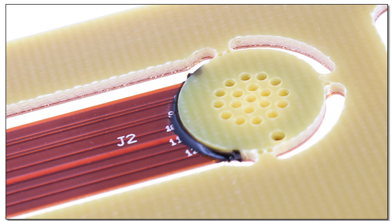
Adding stiffeners to flex and rigid-flex PCBs will add extra processing time, material, and labor, which
can increase costs. As a design tip, stiffeners and overlay terminations on the top and bottom layers
should overlap by at least 0.030 inches to avoid stress points, and keeping all stiffeners the same
thickness reduces processing time during manufacturing.
When selecting the thickness of stiffeners for flex and rigid-flex PCBs, the best way to reduce cost and
lead time is to stick to the most common laminate thicknesses, such as 0.010", 0.031",
0.047" or 0.062", to name a few. Each manufacturer has their inventory of different products,
so it is important to work with them to determine the best common thickness to ensure you are not
specifying a thickness that will create cost and logistics challenges.
Why do we use Stiffeners in Flex Circuit Applications
Flex PCB stiffener requirements include the following categories of use:
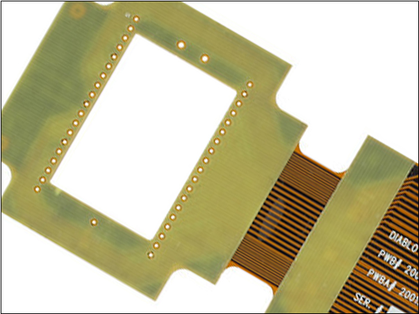
Rigid component/connector area
ZIF (zero insertion force) thickness requirements
Local bend constraints
Component/connector stiffeners
Function:
Creates a localized rigid area over which components/connectors are attached.
Protects solder joints by preventing flex flex in component areas.
Material Options:
FR4, Polyimide, Aluminum, Stainless Steel
Various thicknesses available
Attachment Methods:
Thermal bonding with flexible adhesive
Pressure-sensitive adhesive (PSA)
ZIF stiffeners
Function:
Local thickness increase at contact fingers to meet specific ZIF connector specifications.
Material options:
Polyimide only
Various thicknesses available to meet specific design requirements
Attachment:
Thermal bonding via flex adhesive only
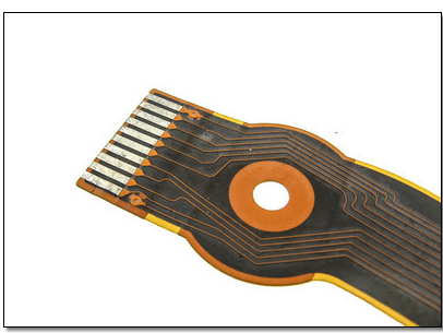
Local Bend Constraint
Function:
Highqualitypcb SMT: Limit the bending area to a specific location in the flexible design to
facilitate final assembly, and achieve specific bending requirements or other end-use requirements.
Material Selection:
FR4, Polyimide
Various thicknesses available
Attachment:
Thermal bonding with flex adhesive
Pressure-sensitive adhesive (PSA)

