Explore RF PCB
This article introduced the mysteries of RF circuit boards.
Explore RF PCB
With the advancement of science and technology, the types of printed circuit boards have become more and
more diverse, and their functions have become more and more complete. Among them, RF-printed circuit
boards are growing rapidly, and their application fields are widespread. This article will take you to
explore the mysteries of RF circuit boards.

What is Radio Frequency?
RF stands for Radio Frequency, which indicates the frequency of electromagnetic waves that can be
radiated into space, ranging from 300kHz to 300GHz. Radiofrequency is radio frequency current,
abbreviation of a high-frequency alternating electromagnetic wave. An alternating current that changes
less than 1,000 times per second is called a low-frequency current, and an alternating current that
changes more than 10,000 times per second is called a high-frequency current. And radio frequency is
such a high-frequency current.
In electronics theory, electromagnetic waves refer to the electromagnetic fields formed by alternating
current passing through a conductor.
When the frequency of electromagnetic waves is lower than 100kHz, the Earth's surface absorbs them and
cannot form effective transmission. However, when the frequency of electromagnetic waves is higher than 100kHz, electromagnetic waves can propagate in the air and transmit signals over long distances. High-frequency
electromagnetic waves with long-distance transmission capabilities are called radio frequencies.
What is the role of radio frequency?
RF's function is to transmit information wirelessly. It uses high-frequency electromagnetic waves (radio
frequency) to achieve long-distance communication. It can propagate in the air and reflect through the
ionosphere at the outer edge of the atmosphere, thus forming an effective long-distance transmission
capability. Radio frequency technology is widely used in wireless communications, radar systems, medical
equipment, and other fields.
Characteristics of radio frequency
Radio-frequency (RF)has the following characteristics:
High frequency: The frequency of radio frequency waves is high and can transmit more data information.
Strong long-distance transmission capability: The transmission distance of radio frequency waves is
longer than that of ordinary electromagnetic waves and is suitable for communication equipment with a
wide range.
Strong penetration: Radio frequency waves can penetrate obstacles such as walls, mountains, forests,
buildings, etc. They can cover a wide range of communication signals and complete signal transmission.
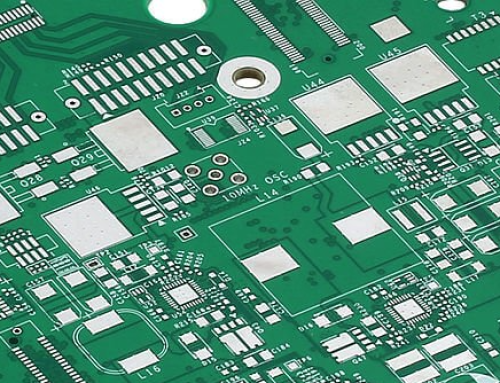
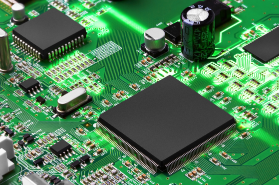
What is an RF PCB?
RF-printed circuit boards are one of the types of high-frequency circuit boards. RF PCB is a high-frequency board made using radio frequency technology. RF circuit board is a very high-speed
circuit with a frequency of 100mhz and above, generally between 500mhz-2ghz. Above 2ghz is a microwave
PCB.
Therefore, the difference between rfPCB and microwave circuit board lies in frequency. There are also some differences in circuit board design.
Radio frequency circuits can be designed using lumped parameter components or mixed parameter
components.
Since the size of microwave circuits is almost the same as their wavelength, they must be designed using
distributed parameter components.
Characteristics of RF-printed circuit boards
The manufacturing of RF-printed circuit boards is so strict and requires more sophisticated mechanical
equipment, such as plasma etching machinery, laser direct imaging (LDI), etc. With the support of this
precision equipment and RF technology, RF circuit boards have the following characteristics:
1) Strong temperature control capability
The thermal conductivity of RF-printed circuit boards is lower than that of ordinary printed circuit
boards made of FR-4 material. It means they can operate under high-temperature conditions for a long
time without being damaged.
2) High frequency
Compared with other circuit boards, their electromagnetic wave frequency is higher, so the signal
transmission distance is longer and can cover a large area, allowing wireless communication equipment to
transmit information in time
3) Strong stability
The RF PCB substrate material is polytetrafluoroethylene (PTFE), which has a lower coefficient of
thermal expansion (CTE) than traditional FR4. Therefore, the RF board is more stable in high-temperature
environments.
When designing a PCB, you can mix PTFE materials and FR4 to build a PCB stack up and reduce the board
area. Since FR4 is cheaper, it can also reduce production costs.
What materials do you need for RF circuit boards?
The material needs to be selected based on factors such as dielectric constant (DK), dissipation factor
(DF), coefficient of thermal expansion (CTE), manufacturability, passive intermodulation (PIM), cost
considerations, etc. Different materials have different application scenarios, so when designing, it is
necessary to consider and evaluate the project in many aspects to meet the design performance
requirements.
1) Polytetrafluoroethylene (PTFE)
PTFE is very popular in RF design due to its low thermal expansion coefficient, high dielectric
constant, and stable performance, such as Teflon and Rogers materials.

2) FR-4
Fr- stands for flame retardant. FR -4 is one of the most common PCB materials. Its price is relatively
low compared to PTFE. It is generally suitable for electronic devices. However, in higher-frequency RF
applications, the high thermal expansion coefficient of FR-4 will be limited.
3) RO4000 Series
It is a specific series of PTFE or glass fiber composite materials. Low Dk and low loss, suitable for
high-frequency circuit design, reduce passive intermodulation (PIM) performance and provide better
stability.
4) RO3000 Series
Similar to RO4000, the RO3000 series is also a PTFE-based material but has different dielectric
constants and other properties, suitable for different RF designs. Models include: RO3003, RO3006,
RO3010, RO3035 high frequency laminates.
5) Aluminum-based printed circuit boards
Suitable for high-power radio frequency fields, this circuit board generally uses an aluminum substrate
to improve heat dissipation and electrical properties.
6) Metallized ceramics
It is used in some very high-frequency and microwave-frequency devices. The metalized ceramic PCBs can
provide lower dielectric loss and excellent stability.
Application of RF circuit boards
1) Communications
Radiofrequency technology is significant in wireless communications, such as mobile communications,
satellite communications, wireless broadcasting, radar, and other fields.
2) Electronic radio frequency equipment field
Radiofrequency technology plays a vital role in electronic devices, such as televisions, radio stations,
microwave ovens, and other fields.
3) Medical and life sciences
Radiofrequency technology is widely used in medical and life science fields, such as medical imaging,
drug development, and biological testing.
4) Electronic games
Radiofrequency technology is widely used in electronic games, such as wireless microphones, wireless
controllers, near-field communications, etc.
5) Aerospace
Radiofrequency technology is also indispensable in artificial satellites and space exploration, such as
orbit control, satellite communications, etc.
To sum up, radio frequency technology is widely used in various industrial and scientific fields and
plays a crucial role.
What factors should be considered in RF PCB design?
There are many factors to consider when designing a circuit board, such as parameter settings,
manufacturing costs, manufacturability, etc. Among them, parameter settings are crucial because they
affect the practical performance of the circuit board.
In RF board design, you can achieve the best performance of the circuit board.
1) Impedance matching
It is important to reduce circuit signal loss, and proper impedance matching can ensure power transmission efficiency between components. This process mainly considers the line width, spacing,
substrate material, and routing configuration.
2) Cable routing design
Signal transmission is propagated through the traces, so the layout of the traces is significant. It is
easily affected. It is generally best to have coplanar and short traces to reduce losses and improve
performance.

3) Through hole utilization
It may generate parasitic capacitance (unintended capacitance), which can cause signal distortion.
Therefore, in the design, vias should be reduced as much as possible, the hole size should be kept
uniform, and specific vias should be ensured for the pins or pads.
4) Ground planes and vias
5) Power supply decoupling
RF circuit boards require noise reduction to be effective, and power supply decoupling is one way to
remove noise. Selecting decoupling capacitors can eliminate all power supply-introduced noise, so it is
critical to place the capacitors carefully.
• RF components and capacitors should be placed on the same side
• Each capacitor must have a ground via
• The capacitor with the lowest power is placed near the power supply and is arranged from large to small.
RF PCB Manufacturing (Special Processes and Technologies)
The manufacturing process of RF circuit boards is somewhat different from that of traditional circuit
boards. In order to maintain the performance and stability of high-frequency circuits, there are some
key manufacturing processes.
1) Material selection
Due to its high-frequency performance, it is vital to select the material. Common materials include
polytetrafluoroethylene (such as Teflon and RO4000 series materials ).
2) Imaging, lamination, etching
RF circuit boards have high requirements for precision, so laser imaging machines are used in the
imaging stage, and plasma etching machines are used during etching. It ensures the circuit accuracy
meets the design requirements.

3) Control board thickness
Board thickness affects the electrical stability between circuits, so it must be consistent during PCB
manufacturing flow.
RF circuit testing
1) Impedance test
Impedance matching testing must be done during the circuit board manufacturing. It affects signal loss. The
test ensures that the circuit impedance is consistent with the designed impedance. Generally, the time
domain reflection test (TDR) is used.

2) Functional loss test
Test the loss characteristics of RF PCB within the designed power range to ensure that the signal
transmission quality is not affected by excessive loss. Common test methods include:
•Frequency conversion method
•Transmission Line Method
•Heat balance method
•DC Power Measurement Method

3) Environmental adaptability test
Test the circuit board under different temperature and humidity conditions to evaluate its stability and
reliability in different environments.
Future trends
With the rapid development of the Internet of Things, 5G communications, smart homes, and other fields,
the demand for the RF PCB market is showing a rapid growth trend, promoting further innovation and
market competition in RF technology.
